Maintenance of overhead power lines
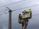 Maintenance of overhead power lines (OHL) includes inspections (of various types), preventive checks and measurements and removal of minor damages.
Airline inspections are divided into periodic and extraordinary. In turn, periodic inspections are divided into day, night, riding and control.
Daily examinations (the main type of examinations) are carried out once a month. At which visually checked the condition of overhead line elements, overhead line elements are examined through binoculars. Night inspections are carried out to check the condition of power connections and street lighting.
During riding inspections, the overhead line is disconnected and grounded, the fastening of insulators and fittings, the condition of the wires, the tension of the wires, etc. are checked. If necessary, night and riding inspections are planned.
Control inspections of individual sections of the line are carried out by engineering and technical personnel once a year in order to check the quality of the work of electricians, assess the condition of the route and implement emergency measures.
Extraordinary inspections are carried out after accidents, storms, landslides, severe frosts (below 40°C) and other natural disasters.
The list of work performed during the maintenance of overhead power lines includes:
-
checking the condition of the track (presence of foreign objects and random structures under the wires, fire condition of the track, deviation of supports, distortion of elements, etc.);
-
assessment of the condition of the wires (the presence of breaks and melting of individual wires, the presence of excesses, the size of the sag, etc.);
-
checking supports and racks (condition of supports, presence of placards, integrity of grounding);
-
monitoring of the condition of insulators, switching equipment, cable bushings on slopes, limiters.
Air line status check
When checking the route of the overhead line, an electrician checks security zone, clearance, breaks.
The protection zone L is determined by straight lines 1 (Fig. 1), at a distance from the protrusion of the end wires 2 at a distance of 1, which depends on the nominal value of the voltage of the overhead line (for overhead lines up to 20 kV inclusive , 1 = 10 m ).
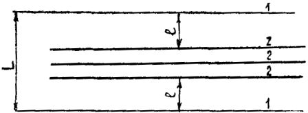
Rice. 1. Security area
The mountains line up as the line passes through forests and green spaces. In this case, the width of the meadow (Fig. 2) C = A + 6m at h4m, where C is the normalized width of the meadow, A is the distance between the end wires, h is the height of the trees.
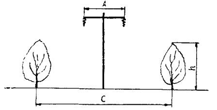
Rice. 2. Determining the width of the meadow
In parks and reserves, it is allowed to reduce the width of the meadow, and in orchards with a tree height of up to 4 m, the clearing of the meadow is optional.
The distance is determined by the horizontal distance from the end conductors of the line at their greatest deviation to the nearest projecting parts of the building or structure. For overhead lines up to 20 kV, the gap must be at least 2 m.
It is forbidden to place hay and straw, wood and other combustible substances in the security area, because if ignited, an earth fault may occur. Excavation works, laying of communications, roads, etc., are prohibited in the vicinity of wires and supports.
When passing overhead lines with wooden supports in places where ground fires are possible, around each support within a radius of 2 m, the ground must be cleared of grass and bushes, or reinforced concrete attachments must be used.
The practice of operating overhead power lines shows that often the cause of accidents is the violations of the rules for the protection of lines and improper actions of the population (throwing foreign objects on the wires, climbing on supports, launching kites, using long poles in the security zone and others.). Emergency situations can also occur when mobile cranes, aerial platforms and other equipment over 4.5 m in height pass under power lines outside the roads.
When carrying out work near overhead lines with the help of mechanisms, the distance from their retractable parts to the wires must be at least 1.5 m. When crossing the road with overhead lines on both sides, warning signs are installed indicating the permissible height for carriage with cargo.
The management of the organization operating the network must carry out explanatory work with production personnel about the characteristics of work near overhead power lines, as well as among the population about the inadmissibility of violations of the rules of line protection.
Checking the position of the supports
When checking the route of the overhead line, the degree of deviation of the supports above the permissible norms from the vertical position, along and along the line, is monitored. The reasons for the deviation can be soil settling at the base of the support, improper installation, poor fastening at the points of connection of the parts, loosening of the clamps, etc. The inclination of the support creates additional stress from its own weight in dangerous areas of the ground and can lead to a violation of mechanical strength.
The deviation of the vertical parts of the support from the normal position is checked with a plumb line (Fig. 3) or with the help of surveying tools. The change in the position of the horizontal parts is checked by eye (Fig. 4) or with the help of a theodolite.
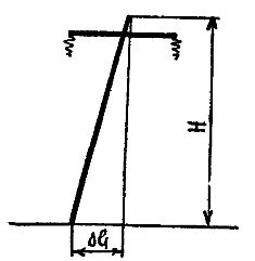
Rice. 3. Determination of the position of the supports
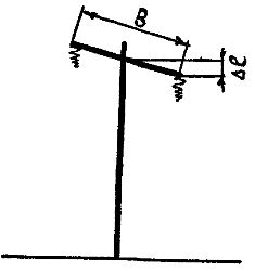
Rice. 4. Determining the position of the crosshead
When determining the plumb slope, it is necessary to move away from the support at such a distance that the plumb line protrudes at the top of the support. Observing the plumb line of the earth's surface, they notice an object. After measuring the distance from it to the axis of the base of the support, the size of the slope is determined. More accurate measurement results are obtained using special geodetic tools.
Checking the condition of the supports
 When inspecting reinforced concrete supports, the main attention should be paid to the identification of visible defects. Such defects include poor adhesion of the reinforcement to concrete, one-sided displacement of the reinforcing cage relative to the axis of the bearing shaft.
In any case, the thickness of the protective concrete wall must be at least 10 mm. Cracks are checked especially carefully, because during further operation they lead to corrosion of the reinforcement and destruction of the concrete, mainly at the level of groundwater. For reinforced concrete supports, no more than 6 ring cracks per meter with a width of up to 0.2 mm are allowed.
It should be borne in mind that the roll of reinforced concrete supports along the line contributes to an increase in cracking, since due to the large weight of the support, the probability of its overstressing increases. Proper decamping is also important.
Poor backfilling and tamping of the foundation pit will cause the support to roll and may break. Therefore, in the first and second year after commissioning, the supports are checked especially carefully and they are corrected in a timely manner.
Mechanical damage to reinforced concrete supports is possible due to incorrect organization of installation and restoration works, as well as in case of accidental vehicle collisions.
The main disadvantage of wooden supports is putrefaction… The process of wood destruction is most intense at a temperature of + 20 ° C, wood humidity 25 — 30% and sufficient access to oxygen. The most quickly destroyed places are attachments on the earth's surface, stands in the end part and in the places of articulation with the step and the traverse.
The main means of combating wood damage is the impregnation of the carrier material with antiseptics. When servicing overhead power lines, the degree of decay of the wood of the supporting parts is periodically monitored. In this case, the places of decay are determined and the depth of spread of decay is measured.
In dry and frost-free weather, the support is tapped to detect core rot. A clear and ringing sound characterizes healthy wood, a dull sound indicates the presence of rot.
To check the decay of attachments, they are dug to a depth of 0.5 m. The amount of rot is determined in the most dangerous places — at a distance of 0.2 — 0.3 m below and above ground level. Measurements are made by drilling a wooden support with fixation of the applied force. A prop is considered strong if a force of more than 300 N is required to break through the first layers.
Depth of decay was determined as the arithmetic mean of three measurements. The affected area should not exceed 5 cm with a support diameter of 20 — 25 cm, 6 cm with a diameter of 25 — 30 cm and 8 cm with a diameter of more than 30 cm.
In the absence of a device, you can use a conventional gimbal. In this case, the depth of decay is determined by the appearance of the sawdust.
For non-destructive testing of the presence of decay in the wood details of the supports, the decay determinant has recently been used. This device works on the principle of fixing changes in ultrasonic vibrations when passing through wood. The indicator of the device has three sectors — green, yellow, red, respectively, to determine the absence of decay, slight and severe decay.
In healthy wood, vibrations propagate practically without damping, and in the affected part there is a partial absorption of vibrations. The ID consists of an emitter and a receiver that is pressed against the controlled wood on the opposite side. With the help of the rotting determinant, it is possible to roughly determine the condition of the wood, in particular to decide on lifting to the support for the production of work.
After the control is completed, if a hole is made in the tree, it is closed with an antiseptic.
On overhead lines with wooden supports, in addition to decay, the supports can ignite from the action of leakage leaks with contamination and defects in insulators.
Checking wires and cables
 After the appearance of the first damage to the cores in the conductor, the load on each of the others increases, which accelerates the process of their further destruction until a break.
If the wires break more than 17% of the total cross-section, a repair sleeve or bandage is installed. Applying a bandage to the place where the wires are broken prevents further unwinding of the wire, but mechanical strength is not restored.
The repair sleeve provides strength up to 90% of the strength of the whole wire. With a large number of hanging wires, they resort to installing a connector.
Rules for Electrical Installation (PUE) normalizes the distance between wires, as well as between wires and the ground, wires and any other devices and structures located in the area of the overhead line route.So, the distance from the wires to the ground of the 10 kV overhead line should be 6 m (in hard-to-reach areas — 5 m), to the roadway — 7 m, to communication and signal wires — 2 m.
Dimensions are measured during acceptance tests, as well as during operation, when new junctions and structures appear, when replacing supports, insulators and fittings.
An important feature that allows you to control the change air line sizes, is the wire sag arrow. The sag arrow is understood as the vertical distance from the lowest point of the wire sag in the distance to the conditional straight line passing at the level of the height of the wire suspension.
Geodetic goniometric devices, for example, theodolite and rods, are used to measure dimensions. The work can be carried out under tension (insulating rods are used) and with tension relief.
When working with the bus, one of the electricians touches the conductor of the overhead line with the end of the bus, the other measures the distance to the bus. A drooping arrow can be checked by aiming. For this purpose, the lamellae are fixed on two adjacent supports.
The observer is on one of the supports in such a position that his eyes are level with the staff, the second rail moves along the support until the lowest point of sag is on a straight line connecting the two guide bars.
The sag arrow is defined as the arithmetic mean distance from the suspension points of the wires to each rail. Airline dimensions must meet PUE requirements. The actual sag arrow should not differ from the design by more than 5%.
Measurements take ambient temperature into account. Actual measured values are reduced to data at a temperature that provides the maximum sag value using special tables. It is not recommended to measure the dimensions when the wind is more than 8 m / s.
Checking the condition of the insulators
Analysis of the performance of overhead power lines shows that about 30% of overhead line damage is related to insulator failures... The reasons for the failure are varied. Relatively often, insulators overlap during a thunderstorm due to loss of dielectric strength of several elements in the string, with increased mechanical forces due to ice and conductor dance. Bad weather contributes to the process of contamination of insulators. Overlapping can damage and even destroy insulators.
During operation, there are often cases of annular cracks appearing on insulators due to improper sealing and temperature surges from direct sunlight.
An external examination checks the condition of the porcelain, the presence of cracks, chips, damage and dirt. Insulators are recognized as defective if cracks, chips occupy 25% of the surface, the glaze melts and burns, and persistent contamination of the surface is observed.
Sufficiently simple and reliable methods for monitoring the serviceability of insulators have been developed.
The simplest method to detect a broken insulator is to check the presence of voltage on each element of the garland... A rod 2.5 — 3 m long with a metal tip in the form of a fork is used.When checking, one end of the plug touches the caps on one insulator and the other on the adjacent one. If no spark occurs when the end of the plug is removed from the cap, the insulator is broken. Specially trained electricians are allowed to carry out this work.
A more accurate method is to measure voltage in an insulator... The insulator rod has a stop at the end with an adjustable air gap. Discharge is achieved by placing the rod plug on the metal caps of the insulators. The size of the gap indicates the value of the breakdown voltage. Absence of damage indicates isolator failure.
On de-energized overhead lines, in order to monitor the condition of the insulators, the insulation resistance is measured with a megohmmeter with a voltage of 2500 V. The resistance of each insulator should not be less than 300 megohms.
Various fittings are used to fasten wires and insulators: clamps, earrings, ears, cradles, etc. The main cause of failure of fittings is corrosion. In the presence of aggressive components in the atmosphere, the corrosion process is accelerated. Reinforcement can also collapse due to fusion when the insulation string overlaps.