Visual inspection in electricity
Visual control consists of checking the condition of certain elements of equipment, materials, liquids, etc. in order to promptly identify signs of their unsuitability for further exploitation and accordingly prevent the threat of an emergency situation as a result of their damage.
Visual control in electricity is one of the main types of control that is carried out during the operation of various electrical installations and electrical networks.
In this article, we will consider how visual control is carried out in the power industry, we will give its purpose and the consequences of not implementing this measure.
Considering the issue of visual control, it can be divided into several stages, depending on the category of the inspected equipment in electricity.
1. Isolation of equipment
Insulation in electricity is an integral part of the design of almost all electrical equipment.In the event of a violation of the integrity of the insulating materials or deterioration of their dielectric properties, emergency situations may occur, and there is also a risk of electric shock to people servicing electrical installations or in the immediate vicinity of them. Therefore, one of the main stages of visual inspection in the electric power industry is the inspection of insulating materials.
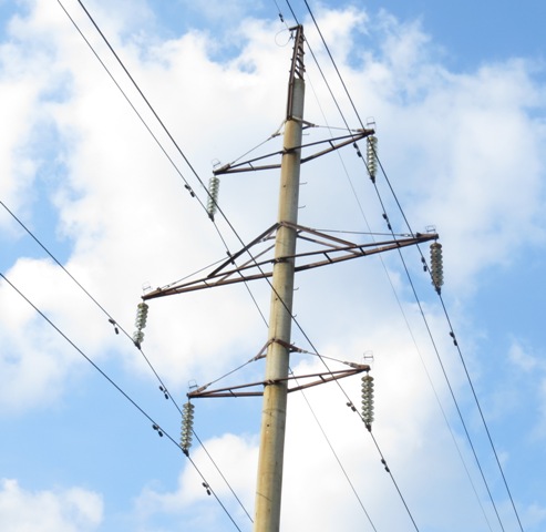
In this case, we are talking about the inspection of insulators (sleeves, supports, suspended, traction, linear, rigging) equipment of switchgear and overhead power lines.
The visual inspection of insulators is reduced to the timely detection of chips and cracks, the area of which is higher than the permissible values for a certain type of insulator. Also pay attention to the contamination of the insulation, which can lead to overlap and accident, especially equipment damage and electric shock to people.
As for the cable lines, in most cases they are laid in places where there is no possibility of inspection, therefore, a deterioration in the quality of the cable insulation can only be detected by conducting appropriate tests with increased voltage.
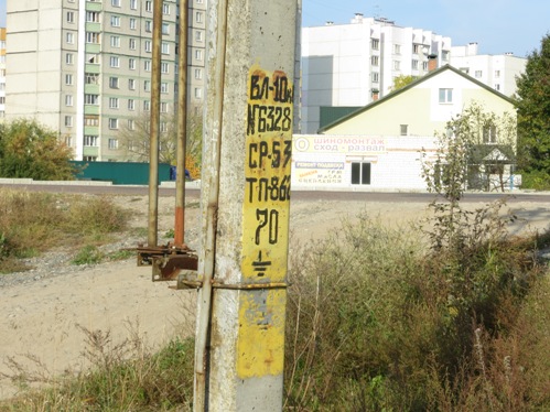
2. Metal and reinforced concrete structures of equipment, supports
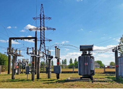
Almost all the equipment of open distribution substations is mounted on metal structures or with the help of reinforced concrete supports. When performing equipment checks, it is necessary to pay attention to the condition of these elements in order to detect possible damage in time.
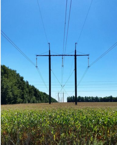
The same applies to metal and reinforced concrete poles of overhead power lines.Their inspection is carried out both in a planned mode and in the event of a power line failure in order to detect damage, one of the reasons for which may be the fall of the support or violation of its integrity.
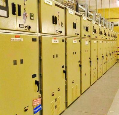
3. Busbars, busbars, power lines and cable lines
Busbars, system busbars and bus sections are used to distribute electricity in switchgear, then the electricity is transmitted directly to consumers or to other distribution substations via overhead power lines and cable lines, where further conversion and distribution of electricity takes place. Load currents flow through them, which is why it is very important that these elements are in good technical condition.
The visual inspection of the above current-carrying elements is to check the absence of external damage, the reliability of their attachment to the insulators. Particular attention is paid to the contact connections of wires, busbars, busbars to each other, as well as to the contact terminals of other elements electrical equipment of substations — switches, disconnectors, surge arresters, current and voltage transformers, compensating devices, power transformers, etc.
Decreasing the reliability of the contact connection in the presence of sufficient load will lead to overheating of the contact connections. Therefore, in the process of visual inspection, attention is paid to the external condition of the contacting elements.
Overheating of contact joints can be detected by a change in the color of the metal near the contact, and in case of excessive overheating, by melting of the contact surfaces.Also signs of overheating are the presence of signs of destruction of nearby surfaces made of materials that are not resistant to high temperatures, as well as destruction of paint.
In the distribution devices of substations, for the timely detection of a violation of the contact connections, special signaling devices are installed on the contact connections.
In open-type switchgear, disposable temperature indicators made of low-melting metal are often used. If the contact connection heats up, the low-melting metal melts and the signaling device falls. In this way, overheating of the contact connections can be detected in a timely manner.
There are also film-type indicators that change color depending on the temperature of the contact connection.
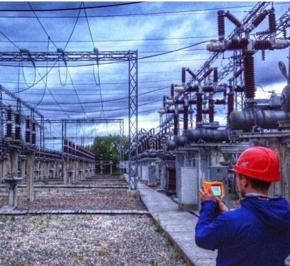
For the timely detection of damaged sections of current-carrying elements, excessive overheating of contact connections, structural elements of distribution equipment and power lines, a full inspection is periodically carried out using thermal imagers… Control of the thermal image allows you to determine with high accuracy the place of overheating and its temperature.
Also, the visual control provides for the inspection of parts under voltage for coronation — identification of the so-called. Corona discharges. Coronation can occur both on overhead power lines and in open-type switchgear. This phenomenon leads to significant losses in electrical networks, so this phenomenon must be promptly registered and eliminated. Inspection of coronation equipment is carried out, as a rule, in the dark, preferably in wet weather.
4. Grounding devices
Grounding devices in the electrical industry serve several functions. First of all, they ensure the safety of personnel servicing electrical installations from electric shock. In switchgear and on overhead power lines, grounding devices provide protection against lightning surges by diverting the lightning discharge into a lightning rod or lightning protection cable, or by diverting an unwanted surge impulse that has fallen out of phase through a surge arrester or surge arrester that are connected to the ground chain.
The grounding loop is used to ground the neutral of the power transformer in the case of its operation in solidly grounded or effectively grounded neutral mode. In electrical networks up to 1000 V, when consumers are powered according to the TN-CS grounding scheme, the grounding loop is used not only for neutral grounding, but also for re-grounding the supports of the power line to prevent the consequences of breaking the zero (combined) power line conductor.
The visual inspection of the grounding circuit in electrical installations and along power lines is reduced to checking the integrity of the relevant elements, the correctness of their connection, depending on the type and mode of operation of the inspected elements.
Untimely detection of faults on the ground loop can lead to emergency situations in the electrical network, as well as accidents due to the lack of protective grounding.
5. Electrical materials
Visual control in the power industry also includes control over the condition of various electrical materials that are used in the power industry — transformer oil, silica gel, SF6 gas, lubricants and fluids, semiconductor, magnetic and other materials.
For example, in a power oil transformer, the oil level in the tank expander is checked, as well as its temperature, the condition of the signal silica gel in the air dryer; in the SF6 breaker, the pressure level of the SF6 gas in the tank is checked, etc.
Visual inspection does not allow detection of changes in the chemical composition of transformer oil, gases, etc., affecting the deterioration of the quality of equipment operation. Therefore, in addition to visual control, it is necessary to carry out periodic chemical analyzes and other studies of the relevant electrical materials.
7. Indications for devices and different devices
Visual control also provides for control and recording in the relevant registers of the readings of various measuring devices (ammeters, voltmeters, wattmeters), position indicators of various equipment elements, recording emergency processes, frequency relays, differential protection relays, counters on - off cycles of switches, temperature sensors, etc.
The monitoring of the indications is necessary to maintain the necessary mode of operation of the electrical network, to prevent possible emergency overloads and other emergency modes of operation.This stage of management is no less important, since untimely detection of abnormal operation can lead to equipment damage.
It should also be noted that visual inspection is the most important measure when commissioning new or technically re-equipped electrical equipment. In this case, a number of measures are taken to control the condition of materials and equipment at all stages — upon receipt, during installation work, during setup and preparation for commissioning.
Visual control, as mentioned above, serves to promptly identify signs of electrical equipment malfunction and accordingly prevent emergency situations, including threats to human life. Visual control is a complex activity, therefore the performance of any part of it cannot be neglected. In addition, it should be borne in mind that not all malfunctions, violations of normal operation can be identified by visual inspection.
The decrease in the dielectric strength of the insulation of the equipment and cable lines, the change in the chemical composition of the transformer oil, the wear of parts of the mechanical components of the equipment, the deviations of various parameters from the maximum permissible values and other internal malfunctions are identified, as a rule, during scheduled preventive maintenance, electrical laboratory tests and additional measurements.
Therefore, when using equipment in the power industry, it is necessary to approach the issue of monitoring its condition in an integrated way, combining visual control with other management methods.