Operation of entire transformer substations
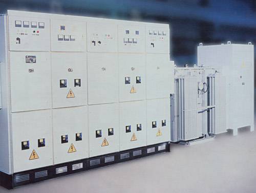
Complete transformer substation (KTP) Electrical installation designed to receive, transform and distribute three-phase electricity. It consists of one or two transformers, a high voltage device (UVN) with switching equipment, a complete distribution device on the low voltage side (LVSN) and serves to distribute energy between individual electrical receivers or groups of electrical receivers in the store.
The conventional designation of the entire transformer substation KTP -X / 10 // 0.4-81 -U1 is deciphered as follows: K — complete, T — transformer, P — substation, X — power of the power transformer (25, 40, 63 , 100, 160), kVA, 10 — voltage class in kV, 0.4 — nominal voltage on the LV side, 81 — year of development, U1 — type of climate modification.
Operating conditions of complete transformer substations
The installation height of the transformer above sea level is not more than 1000 m.
Ambient temperature from -40 to +40 degrees C.
No shaking, vibrations, shocks.
The environment is non-explosive, chemically inactive.
The warranty period is three years from the date of commissioning of the transformer substation.
Complete transformer substation KTP-250-2500 / 10 / 0.4-U3
The complete transformer substation KTP-250-2500 / 10 / 0.4-U3 includes:
1. The device on the high voltage side (UVN) is a bushing cabinet VV-1 or a ШВВ-2УЗ cabinet with a load switch VNP.
2. Power transformers (one for KTP, two for 2KTP): -oil TMF-250, TMF-400-for KTP-250-400; -oil TMZ and dry TSZGL -for KTP -630, -1000, -1600, -2500.
3. Low-voltage switchgear LVSN 0.4 kV, consisting of input cabinets for low voltage, sectional cabinet for two-transformer substation and cabinets of outgoing lines.
Protection of entire transformer substations from short circuit closures
KTP protection against multi-phase short circuits on outgoing lines is carried out by means of switches with built-in electromagnetic and thermal releases.
Connection of a complete transformer substation when radial supply
When radially feeding the KTP with cable lines from the 6-10 kV distribution point according to the block-line-transformer scheme, a dead connection to the transformer is allowed.
Connection of a complete transformer substation when backbone supply
The installation of a UVN cabinet with disconnection and earthing equipment in front of the KTP transformer with the main supply circuit is mandatory.
At transformer power 1000 — 1600 kVA, two or three KTP should be connected to one main line, at lower powers — three or four.
Connection of entire 2500 kVA transformer substations
KTP with transformers with a capacity of 2500 kVA should be fed in a radial scheme, since it is difficult to carry out selective protection of the supply line in a trunk scheme with two transformers.
Placement of in-store KTP
Complete transformer substations in the shop are usually located on the ground floor in the main and auxiliary premises of the production.
Maintenance of complete transformer substations
At support complete transformer substations (KTP), the main equipment that must be monitored and maintained regularly are power transformers and switchboard switching equipment.
The manufacturer is responsible for the operation of KTP within 12 months from the date of their commissioning, but no more than 24 months from the date of dispatch, subject to the rules of storage, transportation and maintenance.
Load currents during normal operation should not exceed the values specified in the factory instructions. In substations with two backup transformers, the working load should not exceed 80% of the rated one. In emergency mode, overloading of lines departing from switchboards, KTP is allowed when they are protected by automatic machines with combined releases.
In addition to instrument readings, the load on sealed transformers of TNZ and TMZ types is estimated by the pressure inside the tank, which under normal load should not exceed 50 kPa according to the manometer reading. At a pressure of 60 kPa, the pressure switch is activated, squeezing the glass diaphragm and the pressure drops to zero. A sharp drop in internal pressure also occurs when the transformer loses its tightness.
If the pressure drops to zero, check the integrity of the diaphragm. If it is broken, the transformer is turned off and the reason that caused the pressure switch to turn off is found, and in the absence of damage (that is, the relay was triggered by overload), a new membrane is installed and the transformer is turned on at reduced load. Thermometric alarms are installed on sealed transformers to control the temperature in the upper layers of the oil, which act on a light or sound signal in case of overheating.
Schematic diagram of a complete transformer substation (KTP)
BW — Counter, FV1 — FV6 Limiters, T — Power Transformer, S — Circuit Breaker, F1 — F3 Fuses, TA1 — TA3 — Current Transformers, SF1 — SF3 — Circuit Breakers.
In transformers equipped with thermosiphon filters, during operation, the normal circulation of oil through the filter is controlled by heating the upper part of the housing. If contamination is found in the oil sample, the filter is refilled. To do this, the filter is disassembled, the inner surface is cleaned of dirt, sediments and washed with clean dry oil. Replace the sorbent if necessary. The sorbent obtained in a sealed container can be used without drying.
Control of the desiccant is reduced to monitoring the color of the silica gel indicator. If most of them turn pink, the entire desiccant silica gel is replaced or regenerated by heating at 450-500 g C for 2 hours, and the indicator silica gel is heated at 120 g C until the entire mass turns blue (after about 15 hours).
It is recommended at least once a year to remove the deposit and oxide film from the contact system of the step switch by turning the switch up to 15 - 20 times clockwise and counterclockwise.
The frequency of package transformer substation inspections is established by the Office of the Chief Power Engineer. The inspection of the package transformer substation is carried out with complete de-energization of the input and output lines.