How to measure earth resistance
Electrophysical properties of the earth
The electrophysical properties of the ground in which the grounded electrode is located are determined by it resistance... The lower the specific resistance, the more favorable the conditions for the location of the electrode grounding system.
Earth resistance called the resistance between the opposite planes of the cube of the earth with edges of 1 m and is measured in ohms.
To visualize this resistance, recall that a copper cube with 1 m ribs has a resistance of 175-10-6 ohms at 20 °C; so, for example, with a value of p = 100 Ohm-m, the earth has a resistance 5.7 billion times greater than the resistance of copper in the same volume.
Below are the approximate values of earth resistance, Ohm m, at average humidity.
Sand — 400 — 1000 and more
Sandy loam — 150 — 400
Clay — 40 — 150
Clay — 8 — 70
Garden — 40
Chernozem — 10 — 50
Peat — 20
Stone clay (approximately 50%) — 100
Marl, limestone, coarse sand with stones — 1000 — 2000
Rock, stones — 2000 — 4000
River water (in the plains) — 10 — 80
Sea water — 0.2
Tap water — 5 — 60
For the construction of grounded electrodes, it is necessary to know not the approximate, but the exact values of the resistance of the earth at the place of armament. They are determined locally by measurements.
Ground properties can change depending on its condition—humidity, temperature, and other factors—and therefore may have different values at different times of the year due to drying or freezing, as well as the condition at the time of measurement. These factors are taken into account when measuring the resistance of the earth with seasonal coefficients and coefficients that take into account the state of the earth at the time of measurements, so that the necessary resistance of the earthing device is maintained in any season and at any humidity of the earth, i.e. . under unfavorable conditions.
Table 1 shows the coefficients that take into account the condition of the ground during the measurements are given in table.1.
Coefficient k1 is applied if the ground is wet, the measurements were preceded by a large amount of precipitation; k2 — if the soil has normal moisture, if the measurement was preceded by a small amount of precipitation; k3 — if the land is dry, the amount of precipitation is below normal.
Table 1. Coefficients to the measured values of the resistance of the earth, taking into account its state during the measurement
Electrode k1 k2 k3 Vertical
length 3 m 1.15 1 0.92 length 5 m 1.1 1 0.95 Horizontal
length 10 m 1.7 1 0.75 length 50 m 1.6 1 0.8
Measure ground resistance possible with an MC-08 (or similar) four-electrode type device (ground probe). Measurements should be taken during the warm season.
The device works on the principle of a magnetoelectric ratiometer. The device contains two frames, one of which is included as an ammeter, the other as a voltmeter. These windings act on the axis of the device in opposite directions, due to which the deviations of the arrow of the device are proportional to the resistance. The scale of the device is graduated in ohms. The power source for the measurement is a hand-cranked DC generator G. A circuit breaker P and a rectifier Bp are mounted on a common axis with the generator.
Schematic diagram of the earthing measuring device type MS-07 (MS-08)
If the current passes through the end electrodes, then there is a difference in voltage U between the middle ones. The values of U in a homogeneous earth (layer) are directly proportional to the resistance p and the current I and inversely proportional to the distance a between the electrodes: U = ρAz /2πa or p = 2πaU / I = 2πaR, where R is the instrument reading.
The larger the value of a, the larger the volume of the ground covered by the electric field of the current electrodes. Therefore, by changing the distance a, it is possible to obtain the earth resistance values depending on the distance of the electrodes. With a homogeneous basis, the calculated value ρ will not change at. change in distance a (changes may be due to different degrees of humidity). As a result of measurements using the dependence ρ on the distance between the electrodes, it is possible to estimate the value of the resistivity at different depths.
Scheme for measuring earth resistance with the MS-08 device
Measurements should be removed from piping and other structures and parts that may distort the results.
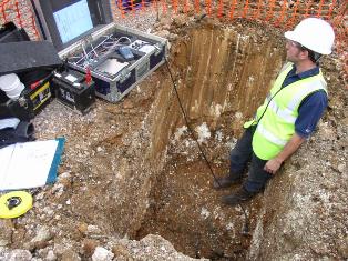
Earth resistance can be roughly measured using the test electrode method. To do this, the electrode (corner, rod) is immersed in the ground in a pit so that its tip is at a depth of 0.6-0.7 m from the ground level, and the resistance of the electrode gv is measured with a device of the MS08 type . And then, using the data on the approximate values of the resistance of the vertical electrodes (table 2), you can get an approximate value of the specific resistance of the ground.
Table 2. Spread resistance of grounding electrodes
Electrode Resistance, ohm Vertical, angle steel, rod, tube ρ / l , where l — length of the electrode in meters 40 mm wide strip steel or round steel with a diameter of 20 mm 2ρ / l , where l — length of the strip in meters Rectangular plate (with a small aspect ratio), placed vertically 0.25 (ρ / (ab-1/2)), where a and b — dimensions of the sides of the plate in m.
An example of calculating soil resistance. A corner 3 m long is sunk into the ground. The resistance measured with the MS-08 device turned out to be 30Ω Then we can write: Rism = rv l = 30NS3 = 90 ohm x m.
It is recommended to take measurements in two or three places and take the average value. The test electrodes must be driven or pressed to make stable contact with the ground; screwing rods for measuring purposes is not recommended.
A similar measurement method should not be used with strips laid in the ground: the method is laborious and unreliable, since proper contact of the strip with the ground after backfilling and tamping can only be achieved after some time.
To take into account the state of the ground during the measurements, one of the coefficients k is taken from the table. 1.
Thus, the ground resistance is equal to: p = k x Rism
The protocol shows the state of the ground (moisture) at the time of the measurements and the recommended seasonal coefficient of freezing or drying of the ground.