Insulation monitoring in networks with isolated neutral
 In networks with an isolated or grounded neutral, during normal operation, the voltages of all three phases to earth are equal to the phase voltage.
In a single-phase earth fault, the voltage of the faulted phase to earth will be zero and that of the unfaulted phases will increase to phase-to-phase. In this case, the phase-to-phase voltages do not change. Such networks can remain in service because damage is difficult to detect. Long-term operation in this mode is unacceptable, because in case of accidental destruction of the insulation of the intact phase, a two-phase short circuit with undesirable consequences will occur.
To monitor the state of insulation in networks with a voltage of up to 1 kV, three voltmeters are used, connected in a star, the neutral point of which is grounded (Fig. 1, a).
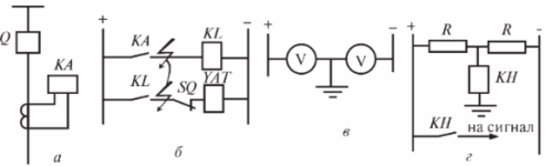
Rice. 1.Single-pole earth fault in two places: insulation control with voltmeters, a — line connection with current transformer, b — relay protection, c — insulation control with voltmeters, d — insulation control with alarm relay, Q — switch, KA — relay for current, KL — intermediate relay, SQ — circuit breaker auxiliary contact, YAT — circuit breaker release solenoid, KH — signal relay, V — voltmeter, R — resistor.
V networks with isolated neutral Insulation control is easy with three voltmeters. The voltmeters are connected to the terminals of the main secondary winding of a three-phase three-winding voltage transformer. Single-phase voltage transformers can also be used for the same purpose.
In networks with voltages above 1 kV, an NTMI voltage transformer is used for monitoring, which has two secondary windings. One coil connected in a star serves to measure the voltage, the second coil connected in an open delta with terminals aΔ — HCΔ — for insulation control with inclusion of an insulation control relay.
A voltage relay is used as this relay. KV acting on the signal (Fig. 2).
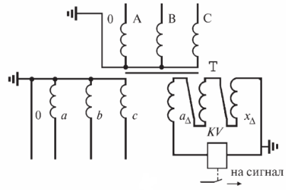
Rice. 2. Isolation control schemes in alternating current circuits in a network with an isolated neutral: O, A, B, C — windings, V — voltmeter, T — NTMI transformer, KV — isolation control relay
In normal mode, the voltage across the terminals of this coil is close to zero. In the case of grounding of any phase in the primary network, the voltage symmetry is broken and a voltage appears on the winding connected in open delta, sufficient to operate the voltage relay, which signals a malfunction.
In the event of a phase insulation failure (short circuit to ground), the voltmeter readings on that phase will decrease and the voltmeter readings on the other two intact phases will increase. In the event of a metal earth fault, the voltmeter of the damaged phase will show zero, and on other phases the voltage will increase by 1.73 times and the voltmeters will show line voltages.
The operating personnel of the substation can also learn about a violation of phase isolation through the operation of the signaling devices. An insulation monitoring relay N is used as a signaling device which is connected to the terminals of the additional secondary winding of the NTMI voltage transformer connected in an open delta circuit. When grounding occurs on the terminals of this coil, a zero-sequence voltage 3U0 occurs, the relay H is engaged and gives a signal (Fig. 3).
In networks in which the compensation of capacitive currents to the ground is carried out using arc suppression reactors, the phase-to-earth signaling devices are connected to the signal winding of the arc reactor or to a current transformer installed at the grounded output of the reactor. To this winding a signal lamp can be connected that lights up when a ground fault occurs in the network. The signal lamp is installed directly in the arc-suppression reactor disconnector drive.
Rice. 3. Control of the state of insulation in networks with isolated neutral: 1 — power transformer; 2 — voltage measuring transformer; H — voltage relay
Finding earth faults
In networks with an isolated neutral and with compensation of capacitive currents, it is possible to operate the network in the presence of an earth fault.However, long-term operation of the network with increased voltage on undamaged phases increases the probability of an accident, and the wire breaking and falling to the ground poses a danger to people. Therefore, detection and elimination of the phase-to-earth fault is carried out as quickly as possible. Simple earth signaling devices in the network cannot determine the location of phase-to-ground, since all sections of the network are electrically interconnected through the substation busbars.
Selective signaling devices USZ-2/2, USZ-ZM are used to determine the electrical circuit with grounding. These devices usually contain a higher harmonic filter and a dial. The harmonic filter operates at a frequency of 50 or 150 Hz (50 Hz for networks without compensation of capacitive currents, 150 Hz for networks with compensation of capacitive currents).
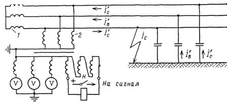
The signaling device is installed on the control panel of the substation or in the corridor of the switchgear b — 10 kV and the zero-sequence current transformer (TTNP) circuits of cable lines are connected to it (Fig. 4).
The setting of the alarm device (control check) is carried out during normal network operation (no grounding) by measuring the levels of higher harmonic currents and unbalance currents with the device at a frequency of 150 Hz. Device readings are compared to these indicators when a broken link is found.
When a stable ground fault occurs in the network, the substation service personnel successively measures the higher harmonic currents in all links and selects the link where the current is highest.
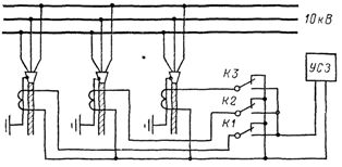
Rice. 4.Single-phase earth fault signaling scheme using USZ
After determining the damaged connection, measures are taken to find and remove the location of the ground fault. HSS devices allow manual identification of a failed link. Recently, however, devices have been developed that automatically determine the stable phase-to-earth fault connection and transmit information via telemechanical channels to the dispatch office of the power grids. A ground fault signaling set of the KSZT-1 (recently KDZS) type has been developed and is widely used.
A simplified block diagram of the device KSZT-1 (KDZS) is shown in Fig. 5.
The device structurally consists of three main blocks:
— BL logic,
— commutation K
— UM indication.
The latter is installed at the dispatching point of the power transmission networks. BL and K blocks are installed at the substation.
When a ground fault occurs in the network, the zero-sequence voltage 3U0 from the voltage transformer winding is fed to the zero-sequence voltage block of BNNP and, if the value exceeds the specified setting, turns on the BL logic block. The logic block controls the operation of the electronic switch K, which sequentially rectifies the zero-sequence current transformers TTNP.
At the end of the TTNP interrogation, the connection with the highest level of higher harmonics is determined in the logic block, the number of which is transmitted in binary-decimal code from the telemechanical device KP-DP to the control center. In the control center, this signal is converted in a decoder into a two-digit number displayed on the UN display, by which the dispatcher visually determines the number of the ground connection.When the ground fault disappears, the whole device automatically returns to its original position.
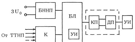
Rice. 5. Block diagram of the device KSZT-1 (KDZS)
The dispatcher has the possibility to call up information about the broken link again by pressing the «Reset» button. In addition, the device allows the operational staff at the substation to search for a broken link by manually interrogating the TTNP. The use of this device can significantly reduce the time of searching for a damaged network section and reduce the probability of developing damage.