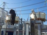
Support of current limiters and arc suppression reactors
 Current-limiting reactors are designed to limit short-circuit currents and maintain a certain level of busbar voltage in the event of a fault behind the reactors.
Reactors are used in substations mainly for networks 6-10 kV, less often for voltage 35 kV. The reactor is a coil without a core, its inductive resistance does not depend on the current flowing. Such an inductance is included in each phase of a three-phase network. The inductive resistance of the reactor depends on the number of its turns, the size, the relative position of the phases and the distances between them. Inductive resistance is measured in ohms.
Under normal conditions, when the load current passes through the reactor, the voltage loss in the reactor does not exceed 1.5-2%. However, when the short-circuit current flows, the voltage drop across the reactor increases sharply. In this case, the residual voltage of the substation buses to the reactor must be at least 70% of the nominal voltage.This is necessary to maintain the stable operation of the other users connected to the substation buses. The active resistance of the reactor is small, therefore the active power loss in the reactor is 0.1–0.2% of the power passing through the reactor in normal mode.
At the switching point, a distinction is made between linear and sectional reactors connected between busbar sections. In turn, linear reactors can be individual (Fig. 1, a) — for one line and group (Fig. 1, b) — for several lines. The design distinguishes between single and double reactors (Fig. 1, c).
Reactor windings are usually made of stranded insulated wire — copper or aluminum. For rated currents of 630 A and above, the reactor winding consists of several parallel branches. In the manufacture of the reactor, the windings are wound on a special frame and then poured with concrete, which prevents the displacement of the turns under the action of electrodynamic forces when short-circuit currents flow. The concrete part of the reactor is painted to prevent moisture penetration. Reactors installed outdoors are subjected to special impregnation.
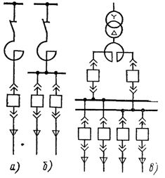
Rice. 1. Schemes for inclusion of current-limiting reactors: a — individual single reactor for one line; b — group unit reactor; with — double reactor of a group
To isolate reactors of different phases from each other and from grounded structures, they are mounted on porcelain insulators.
Along with single reactors, double reactors have found application. Unlike single reactors, double reactors have two windings (two legs) per phase. The windings have one direction of turns.The reactor branches are made for the same currents and have the same inductance. A power source (usually a transformer) is connected to the common terminal and a load is connected to the branch terminals.
Between the branches of the reactor phase there is an inductive coupling characterized by mutual inductance M. In normal mode, when approximately equal currents flow in both branches, the voltage loss in a double reactor due to mutual induction is smaller than in a conventional reactor with the same inductance resistance. This circumstance makes it possible to effectively use a double reactor as a group reactor.
With a short circuit in one of the branches of the reactor, the current in this branch becomes much higher than the current in the other undamaged branch. In this case, the influence of mutual induction decreases and the effect of limiting the short circuit current is mainly determined by the inherent inductive resistance on the reactor branch.
During the operation of the reactors, they are checked. During the inspection, attention is paid to the condition of the contacts at the connection points of the buses to the reactor windings according to the darkened colors, the indicator thermal films, the condition of the winding insulation and the presence of deformation of the turns, to the degree of dustiness and the integrity of the supporting insulators and their reinforcement, to the condition of concrete and lacquer coating.
The wetting of the concrete and the reduction of its resistance are particularly dangerous in case of short circuit and overvoltage in the network due to possible overlapping and destruction of the reactor windings. Under normal operating conditions, the insulation resistance of the reactor windings to ground should be at least 0.1 MΩ.The functionality of the cooling (ventilation) systems of the reactors is checked. If a ventilation malfunction is detected, measures must be taken to reduce the load. Overloading of reactors is not allowed.
Arc Suppression Reactors.
One of the most common faults in the electrical network is the grounding of live parts of an electrical installation. In 6-35 kV networks, this type of damage accounts for at least 75% of all damage. At closing; to the ground of one of the phases (Fig. 2) of a three-phase electrical network operating with an isolated neutral, the voltage of the damaged phase C relative to the ground becomes zero, and the other two phases A and B increase by 1.73 times (up to network voltage ). This can be monitored by the insulation monitoring voltmeters included in the secondary winding of the voltage transformer.
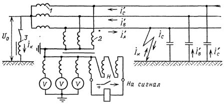
Rice. 2. Phase-earth fault in a three-phase electrical network with compensation of capacitive currents: 1-winding of a power transformer; 2 — voltage transformer; 3 — arc suppression reactor; H — voltage relay
The current of the damaged phase C flowing through the earthing point is equal to the geometric sum of the currents of phases A and B:
where: Ic — earth fault current, A; Uf — network phase voltage, V; ω = 2πf-angular frequency, s-1; C0 is the phase capacitance relative to the ground, per unit length of the line, μF / km; L is the length of the network, km.
It can be seen from the formula that the greater the length of the network, the greater the value of the earth fault current.
A fault between phase and ground in a network with an isolated neutral does not disturb the operation of consumers, since the symmetry of the line voltages is preserved.At large IC currents, earth faults may be accompanied by the appearance of an interrupting arc at the fault site. This phenomenon, in turn, leads to the fact that overvoltages up to (2.2-3.2) Uf appear in the network.
In the presence of weakened insulation in the network, such overvoltages can cause insulation breakdown and phase-phase short circuit. In addition, the thermal-ionizing effect of an electric arc resulting from an earth fault creates a risk of phase-to-phase faults.
Taking into account the danger of earth faults in a network with an isolated neutral, compensation of the capacitive earth fault current using arc suppression reactors is used.
However, research and operational experience show that it is advisable to use arc suppression reactors in 6 and 10 kV networks even with capacitive earth fault currents reaching 20 and 15 A, respectively.
The current flowing through the arc-suppression reactor winding arises as a result of the action of the neutral bias voltage. It, in turn, occurs at neutral when a phase is shorted to ground. The current in the reactor is inductive and directed against the capacitive earth fault current. In this way, the current is compensated at the location of the earth fault, which contributes to the rapid extinction of the arc. Under such conditions, aerial and cable networks can operate for a long time with a phase-to-earth fault.
The change in inductance, depending on the design of the arc suppression reactor, is done by switching the winding branches, changing the gap in the magnetic system, moving the core with direct current.
Reactors of the ZROM type are produced for voltage 6-35 kV.The winding of such a reactor has five branches. In some power systems, arc suppression reactors are produced, the inductance of which is changed by changing the gap in the magnetic system (for example, reactors of the KDRM, RZDPOM type for voltage 6-10 kV, with a capacity of 400 -1300 kVA)
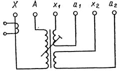
Rice. 3. Scheme of windings of an arc suppression reactor of the RZDPOM type (KDRM): A — X — main winding; a1 — x1 — control coil 220 V; a2 — x2 — signal coil 100 V, 1A.
Arc suppression reactors of a similar type, manufactured in the GDR, Czechoslovakia and other countries, operate in electrical networks. Structurally, arc suppression reactors of the KDRM, RZDPOM types consist of a three-stage magnetic circuit and three windings: power supply, control and signal. The winding diagram is shown in fig. 3. All windings are located on the middle leg of the three-stage magnetic circuit.
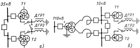
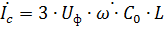
Rice. 4. Schematics for inclusion of arc suppression reactors
The magnetic circuit with coils is placed in a tank of transformer oil. The middle rod is made of one fixed and two moving parts, between which two adjustable air gaps are formed.
In the power coil, terminal A is connected to the neutral terminal of the power transformer, terminal X is grounded through the current transformer. The control coil a1 — x1 is designed to connect an arc suppression reactor (RNDC) regulator.
The signal coil a2-x2 is used to connect control and measuring devices to it. Adjustment of the arc suppression reactor is done automatically using an electric drive. Limiting the movement of the moving parts of the magnetic circuit is done by limit switches.Circuit diagrams for arc suppression reactors are shown in fig.
In fig. 4a shows a universal circuit that allows you to connect arc suppression reactors to any of the transformers. In fig. 4b, the arc suppression reactors are each included in their own section. The power of the arc suppression reactor is selected based on the compensation of the capacitive network earth current supplied by the relevant busbar section.
A disconnector is installed on the arc suppression reactor to shut it down during manual recovery. It is unacceptable to use a switch instead of a disconnector, since the erroneous shutdown of the arc suppression reactor by a switch during grounding in the network will lead to an increase in the current at the grounding point, overvoltage in the network, damage to the insulation of the reactor winding, phase short circuit.
As a rule, arc suppressors are connected to the neutrals of transformers that have a star-delta connection scheme, although there are other connection schemes (in the neutral part of generators or synchronous compensators).
The power of transformers that have no load in the secondary winding and are used to connect arcing reactors to their neutral is chosen equal to the power of the arc suppression reactor. If the transformer for the arc suppression reactor is also used to connect the load to it, its power should be selected 2 times the power of the arc suppression reactor.
Arc Suppression Reactor Setup.Ideally, it can be chosen so that the earth fault current is fully compensated, i.e.

where Ic and Ip are the actual values of the network earthing capacitive currents and the arc suppression reactor current.
This setting of the arc suppression reactor is called resonant (resonance of currents occurs in the circuit).
Regulating the reactor with overcompensation is allowed when

In this case, the earth fault current should not exceed 5 A and the degree of detuning
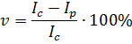
does not exceed 5%. It is allowed to configure undercompensated arc suppression reactors in cable and overhead networks, if any emergency imbalances in the network phase capacities do not lead to the appearance of a neutral bias voltage higher than 0.7 Uph .
In a real network (especially in aerial networks) there is always an asymmetry of the phase capacitance with respect to the ground, depending on the location of the conductors on the supports and the distribution of the coupling capacitors of the phases. This asymmetry causes a symmetrical voltage to appear on the neutral. Unbalance voltage should not exceed 0.75% Uph.
The inclusion of an arc suppression reactor in the neutral significantly changes the potentials of the neutral and the network phases. A neutral bias voltage U0 appears on the neutral due to the presence of asymmetry in the network. In the absence of grounding in the network, the neutral deviation voltage is allowed not higher than 0.15 Uph for a long time and 0.30 Uph for 1 hour.
With the resonant tuning of the reactor, the bias voltage of the neutral can reach values comparable to the phase voltage Uf.This will distort the phase voltages and even generate a false ground signal. In such cases, artificially tripping the arc suppression reactor makes it possible to reduce the neutral bias voltage.
The resonant tuning of the arc suppression reactor is still optimal. And if with such a setting the neutral deviation voltage is greater than 0.15 Uph and the unbalance voltage is greater than 0.75 Uph, additional measures must be taken to equalize the capacity of the network phases by transposing the wires and redistribution of coupling capacitors across the network phases.
During operation, arc suppression reactors are checked: in substations with permanent maintenance personnel once a day, in substations without maintenance personnel — at least once a month and after each earth fault in the network. When examining, pay attention to the condition of the insulators, their cleanliness, the absence of cracks, chips, the condition of the seals and the absence of oil leaks, as well as the oil level in the expansion tank; on the state of the arc suppressor bus, connecting it to the neutral point of the transformer and to the earth loop.
In the absence of automatic adjustment of the reactor to suppress the arc to resonance, its restructuring is carried out by order of the dispatcher, who, depending on the changing network configuration (according to a previously compiled table), instructs the substation duty to switch the branch at the reactor.The duty officer, having made sure that there is no grounding in the network, turns off the reactor, installs the necessary branch on it and turns it on with a disconnector.