Calculation of the resulting resistance in series-parallel connection
Concepts and formulas
 A series-parallel or mixed connection is a complex connection of three or more resistances. The resulting resistance of a mixed connection is calculated in stages using formulas for calculating resistances in series and parallel connections.
Examples of
1. Calculate the series-parallel connection of three resistances according to the diagram in fig. 1.
First, replace the parallel-connected resistances r2 and r3 with the resulting resistance r (2-3):
r (2-3) = (r2 ∙ r3) / (r2 + r3) = (10 ∙ 20) / 30 = 6.6 ohms.
The resulting resistance of the entire circuit is r = r1 + r (2-3) = 5 + 6.6 = 11.6 ohms.

Rice. 1.
2. What current flows through the circuit (Fig. 2) in the open and closed cases knife switch P? How does the voltage across resistance r2 change in both cases?

Rice. 2.
a) The switch is open. Resultant resistance of series connected resistances r1 and r2
r (1-2) = r1 + r2 = 25 ohms.
Current I (1-2) = U / r (1-2) = 100/25 = 4 A.
Voltage drop across resistance r2
U2 = I (1-2) ∙ r2 = 4 ∙ 5 = 20 V.
b) The switch is closed. Resultant resistance of resistors r1 and r3 connected in parallel
r (1-3) = (r1 ∙ r3) / (r1 + r3) = (20 ∙ 10) / (20 + 10) = 200/30 = 6.6 ohms.
The total resistance of the entire circuit is r = r (1-3) + r2 = 6.6 + 5 = 11.6 ohms.
Current I = U / r = 100 / 11.6 = 8.62 A.
The voltage drop across the resistance r2 in this case is equal to: U2 = I ∙ r2 = 8.62 ∙ 5 = 43.25 V.
In the second case, the current increased as a result of connecting the parallel resistance R3. More current creates more voltage drop at resistance r2.
3. What should be additional resistance rd, so that two lamps connected in parallel for a voltage of 120 V and a current of 0.2 A can be connected to a network with a voltage of U = 220 V (Fig. 3)?
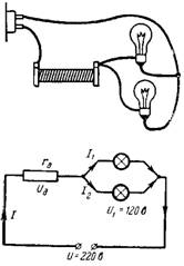
Rice. 3.
The voltage in the lamps should be equal to 120 V. The remaining voltage (100 V) falls on the additional resistance rd. A current of two lamps I = 0.4 A flows through the resistance rd.
According to Ohm's law rd = Ud / I = 100 / 0.4 = 250 Ohm.
4. Electronic lamps with a 1.2 V filament and a filament current of 0.025 and 0.05 A are connected in series to a DC source of voltage 4.5 V. What should be the additional resistance rd and parallel resistance (shunt) to a lamp with a lower filament current (fig. 4)?
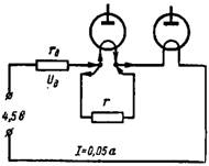
Rice. 4.
The resistances in the circuit must be chosen so that the filament current of the second lamp flows I = 0.05 A. The voltage across the filament of the electronic lamps will be 1.2 + 1.2 = 2.4 V. Subtracting this value from the battery voltage, we take the value of the voltage drop across the additional resistance rd: Ud = 4.5-2.4 = 2.1 V.
Therefore, the additional resistance rd = (Ud) / I = 2.1 / 0.05 = 42 Ohm.
A filament current of 0.05 A should not flow through the filament of the first vacuum tube. Half of this current (0.05-0.025 = 0.025 A) must pass through the shunt r. The shunt voltage is the same as the filament of the lamp, i.e. 1.2 V. Therefore, the shunt resistance is: r = 1.2 / 0.025 = 48 Ohm.
5. What are the resulting circuit resistance and the current in it in the circuit of fig. 5?
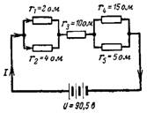
Rice. 5.
First, let's determine the resulting resistance of the parallel-connected resistors:
r (1-2) = (r1 ∙ r2) / (r1 + r2) = (2 ∙ 4) / (2 + 4) = 8/6 = 1.3 ohms;
r (4-5) = (r4 ∙ r5) / (r4 + r5) = (15 ∙ 5) / (15 + 5) = 75/20 = 3.75 ohms.
The resulting circuit resistance is:
r = r (1-2) + r3 + r (4-5) = 1.3 + 10 + 3.75 = 15.05 ohms.
The resulting current at voltage U = 90.5 V
I = U / r = 90.5 / 15.05 = 6 A.
6. Calculate the resulting resistance of a complex series-parallel connection in the circuit of fig. 6. Calculate the resulting current I, current I4 and voltage drop across resistance r1.
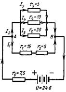
Rice. 6.
Resultant conductance of parallel connected resistances
1 / r (3-4-5) = 1 / r3 + 1 / r4 + 1 / r5 = 1/5 + 1/10 + 1/20 = 7/20 sim;
r (3-4-5) = 20/7 = 2.85 ohms.
The circuit resistance of r1 and r2 is:
r (1-2) = r1 + r2 = 15 + 5 = 20 ohms.
The resulting conductivity and resistance between points A and B are respectively equal: 1 / rAB = 1 / r (3-4-5) + 1 / r (1-2) = 7/20 + 1/20 = 8/20 sim ; rAB = 20/8 = 2.5 ohms.
The resulting resistance of the entire circuit is r = rAB + r6 = 2.5 + 7.5 = 10 ohms.
The resulting current is I = U / r = 24/10 = 2.4 A.
The voltage between points A and B is equal to the source voltage U minus the voltage drop across the resistor r6
UAB = U-I ∙ r6 = 24-(2.4 ∙ 7.5) = 6V.
The resistance r4 is connected to this voltage, so the current through it will be equal to:
I4 = UAB / r4 = 6/10 = 0.6A.
Resistors r1 and r2 have a common voltage drop UAB, so the current through r1 is:
I1 = UAB / r (1-2) = 6/20 = 0.3 A.
Voltage drop across resistance r1
Ur1 = I1 ∙ r1 = 0.3 ∙ 15 = 4.5 V.
7. What are the resulting resistance and current in the circuit of fig. 7 if the source voltage is U = 220 V?
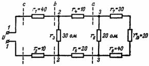
Rice. 7.
We start with the circuit located to the right of nodes 3 and 3. The resistances r7, r8, r9 are connected in series, therefore
r (7-8-9) = r7 + r8 + r9 = 30 + 40 + 20 = 90 ohms.
A resistance r6 is connected in parallel with this resistance, so the resulting resistance at node 3 and 3 (section a)
ra = (r6 ∙ r (7-8-9)) / (r6 + r (7-8-9)) = (20 ∙ 90) / (20 + 90) = 1800/110 = 16.36 ohms.
Resistances r4 and r5 are connected in series with resistance ra:
r (4-5-a) = 10 + 20 + 16.36 = 46.36 ohms.
Resultant resistance of nodes 2 and 2 (section b)
rb = (r (4-5-a) ∙ r3) / (r (4-5-a) + r3) = (46.36 ∙ 30) / (46.36 + 30) = 1390.8 / 76, 36 = 18.28 ohms.
The resulting resistance of the entire circuit is r = r1 + rb + r2 = 40 + 18.28 + 10 = 68.28 ohms.
The resulting current is I = U / r = 220 / 68.28 = 3.8 A.