Voltage drop
Concepts and formulas
 At each resistance r, when the current I passes, a voltage U = I ∙ r appears, which is usually called the voltage drop of this resistance.
If there is only one resistance r in the circuit, the entire source voltage Ust falls on this resistance.
If the circuit has two resistances r1 and r2 connected in series, then the sum of the voltages in the resistances U1 = I ∙ r1 and U2 = I ∙ r2, i.e. voltage drop is equal to the source voltage: Ust = U1 + U2.
The supply voltage is equal to the sum of the voltage drops in the circuit (Kirchhoff's 2nd law).
Examples of
1. What voltage drop occurs across the filament of the lamp with resistance r = 15 Ohm when the current I = 0.3 A passes (Fig. 1)?

Rice. 1.
The number of voltage drops Ohm's Law: U = I ∙ r = 0.3 ∙ 15 = 4.5 V.
The voltage between points 1 and 2 of the lamp (see the diagram) is 4.5 V. The lamp lights normally if the rated current flows through it or if there is a rated voltage between points 1 and 2 (the rated current and voltage are indicated on the lamp).
2. Two identical bulbs for a voltage of 2.5 V and a current of 0.3 A are connected in series and connected to a pocket battery with a voltage of 4.5 V. What voltage drop is generated at the terminals of the individual bulbs (Fig. 2) ) ?

Rice. 2.
Identical bulbs have the same resistance r. When they are connected in series, the same current I flows through them. It follows that they will have the same voltage drops, the sum of these voltages must be equal to the source voltage U = 4.5 V. Each bulb has a voltage of 4, 5: 2 = 2.25V.
You can solve this problem and sequential calculation. We calculate the resistance of the bulb according to the data: rl = 2.5 / 0.3 = 8.33 Ohm.
Circuit current I = U / (2rl) = 4.5 / 16.66 = 0.27 A.
The voltage drop across the bulb U = Irl = 0.27 ∙ 8.33 = 2.25 V.
3. The voltage between the rail and the contact wire of the tram line is 500 V. Four identical lamps connected in series are used for lighting. For what voltage should each lamp (Fig. 3) be selected?
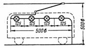
Rice. 3.
Identical lamps have equal resistances through which the same current flows. The voltage drop across the lamps will also be the same. This means that for each lamp there will be 500: 4 = 125 V.
4. Two lamps with a power of 40 and 60 W with a nominal voltage of 220 V are connected in series and are connected to a network with a voltage of 220 V. What voltage drop occurs across each of them (Fig. 4)?
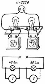
Rice. 4.
The first lamp has a resistance r1 = 1210 Ohm, and the second r2 = 806.6 Ohm (in the heated state). The current passing through the lamps is I = U / (r1 + r2) = 220 / 2016.6 = 0.109 A.
Voltage drop in the first lamp U1 = I ∙ r1 = 0.109 ∙ 1210 = 132 V.
Voltage drop in the second lamp U2 = I ∙ r2 = 0.109 ∙ 806.6 = 88 V.
A lamp with a higher resistance has a larger voltage drop and vice versa. The filaments of both lamps are very weak, but the 40W lamp is slightly stronger than the 60W lamp.
5. In order for the voltage of the electric motor D (Fig. 5) to be equal to 220 V, the voltage at the beginning of the long line (at the power plant) must be more than 220 V in value voltage drop (loss) online. The greater the resistance of the line and the current in it, the greater the voltage drop along the line.
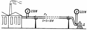 Rice. 5.
In our example, the voltage drop in each wire of the line is 5 V. Then the voltage at the busbars of the power plant should be equal to 230 V.
6. The consumer is powered by an 80 V battery with a current of 30 A. For normal operation of the consumer, a 3% voltage drop in aluminum wires with a cross section of 16 mm2 is permissible. What is the maximum distance from the battery to the user?
Permissible voltage drop in the line U = 3/100 ∙ 80 = 2.4 V.
The resistance of the wires is limited by the permissible voltage drop rpr = U / I = 2.4 / 30 = 0.08 Ohm.
Using the formula for determining the resistance, we calculate the length of the wires: r = ρ ∙ l / S, from where l = (r ∙ S) / ρ = (0.08 ∙ 16) / 0.029 = 44.1 m.
If the user is 22 m from the battery, the voltage in it will be less than 80 V at 3%, i.e. equal to 77.6 V.
7. A telegraph line 20 km long is made of steel wire with a diameter of 3.5 mm. The return line is replaced by grounding through metal busbars. The resistance of the transition between the bus and ground is rz = 50 Ohm.What should the battery voltage be at the beginning of the line if the resistance of the relay at the end of the line is рп = 300 Ohm and the relay current is I = 5 mA?
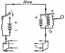
Rice. 6.
The connection diagram is shown in fig. 6. When the telegraph switch is pressed at the point of sending the signal, the relay at the receiving point at the end of the line attracts the armature K, which in turn turns on the coil of the recorder with its contact. The output voltage must compensate for the voltage drop in the line, the receiving relay and the transient resistances of the grounding busbars: U = I ∙ rl + I ∙ rр + I ∙ 2 ∙ rр; U = I ∙ (rр + рр + 2 ∙ rр).
The source voltage is equal to the product of the current and the total resistance of the circuit.
Wire cross-section S = (π ∙ d ^ 2) / 4 = (π ∙ 3.5 ^ 2) / 4 = 9.6 mm2.
Line resistance rl = ρ ∙ l / S = 0.11 ∙ 20,000 / 9.6 = 229.2 ohms.
Resultant resistance r = 229.2 + 300 + 2 ∙ 50 = 629.2 Ohm.
Output voltage U = I ∙ r = 0.005 ∙ 629.2 = 3.146 V; U≈3.2 V.
The voltage drop in the line during the passage of a current I = 0.005 A will be: Ul = I ∙ rl = 0.005 ∙ 229.2 = 1.146 V.
The relatively low voltage drop in the line is achieved due to the low value of the current (5 mA). Therefore, at the receiving point there must be a sensitive relay (amplifier), which is turned on by a weak 5 mA pulse and through its contact turns on another, more powerful relay.
8. How high is the voltage of the lamps in the circuit of fig. 28, when: a) the engine is not switched on; b) the engine starts; c) the engine is running.
The motor and 20 lamps are connected to a 110 V mains supply. The lamps are designed for 110 V and 40 W. The starting current of the motor is Ip = 50 A and its rated current is In = 30 A.
The introduced copper wire has a cross-section of 16 mm2 and a length of 40 m.
Fig. 7 and the conditions of the problem, it can be seen that the motor and lamp current causes the line voltage to drop, therefore the load voltage will be less than 110V.
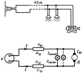
Rice. 7.
U = 2 ∙ Ul + Ulamp.
Therefore, the voltage on the lamps Ulamp = U-2 ∙ Ul.
It is necessary to determine the voltage drop in the line at different currents: Ul = I ∙ rl.
Resistance of the whole line
2 ∙ rl = ρ ∙ (2 ∙ l) / S = 0.0178 ∙ (2 ∙ 40) / 16 = 0.089 Ohm.
The current passing through all the lamps
20 ∙ Ilamp = 20 ∙ 40/110 = 7.27 A.
Grid voltage drop when only lamps are on (no motor),
2 ∙ Ul = Ilamp ∙ 2 ∙ rl = 7.27 ∙ 0.089 = 0.65 V.
The voltage in the lamps in this case is:
Ulamp = U-2 ∙ Ul = 110-0.65 = 109.35 V.
When starting the engine, the lamps will glow more dimly, since the voltage drop in the line is greater:
2 ∙ Ul = (Ilamp + Idv) ∙ 2 ∙ rl = (7.27 + 50) ∙ 0.089 = 57.27 ∙ 0.089 = 5.1 V.
The minimum voltage of the lamps when starting the engine will be:
Ulamp = Uc-2, Ul = 110-5.1 = 104.9V.
When the motor is running, the voltage drop in the line is less than when the motor is started, but more than when the motor is off:
2 ∙ Ul = (Ilamp + Inom) ∙ 2 ∙ rl = (7.27 + 30) ∙ 0.089 = 37.27 ∙ 0.089 = 3.32 V.
The voltage of the lamps during normal engine operation is:
Ulamp = 110-3.32 = 106.68 V.
Even a slight decrease in the voltage of the lamps relative to the nominal significantly affects the brightness of the lighting.