Calculation of potentiometer and compound shunt
Concepts and formulas
 A potentiometer is a variable resistance with a slider that is included as shown in fig.
For more details see — Potentiometers and their applications
A voltage U is applied to points 1 and 2. An adjustable voltage is removed from points 2 and 3, the value of which is less than U and depends on the position of the slider. Voltage dividers have a similar scheme, but they are not adjustable and do not have a movable slider.
Potentiometers, voltage dividers and complex shunts are calculated using Kirchhoff's laws, such as the calculation of conventional circuits with resistances.
Examples of
1. The source voltage is U = 24 V, the total resistance of the potentiometer is r = 300 Ohm. The motor is mounted separately so that r1 = 50 ohms. What voltage U1 can be removed from points 3 and 2 (Fig. 1)?
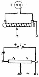
Rice. 1.
The current I and the voltage U across the resistance r are related by the formula I ∙ r = U.
The potentiometer slider separates some of the resistance, ie. the resistance r1. The voltage drop between points 3 and 2 is equal to I ∙ r1 = U1.
From the ratio of the voltage drop, we obtain the equality (I ∙ r1) / (I ∙ r) = U1 / U. The greater the resistance r1, the greater the value of the voltage U1 between points 3 and 2 U1 = r1 / r ∙ U = 50/300 ∙ 24 = 4 V.
2. The potentiometer (Fig. 2) is loaded on a lamp with resistance r = 100 Ohm. The potentiometer is divided by a slider into two parts with r1 = 600 Ohm and r2 = 200 Ohm. Determine the voltage Ul and the lamp current Il.
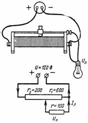
Rice. 2.
Current I flows through resistance r2 and current Il flows through the lamp. A current I-Il flows through the resistance r1, which creates a voltage across the resistance r1 equal to the lamp voltage: (I-Il) ∙ r1 = Ul.
On the other hand, the lamp voltage is equal to the source voltage minus voltage drop at resistance r2: U-I ∙ r2 = Ul.
The current I is equal to the source voltage divided by the resulting resistance of the series-parallel connection of the resistances:
I = U / (r2 + (r ∙ r1) / (r + r1)).
We substitute the expression for the total current of the source in the second equation:
U-U / (r2 + (r ∙ r1) / (r + r1)) ∙ r2 = Ul.
After the transformation, we get an expression for the lamp voltage:
Ul = (U ∙ r1) / (r1 ∙ r2 + r1 ∙ r + r2 ∙ r) ∙ r.
If we transform this expression, starting from the fact that Ul = Il ∙ r, then we get an expression for the lamp current:
Il = (U ∙ r1) / (r1 ∙ r2 + r1 ∙ r + r2 ∙ r).
Substitute the numerical values into the resulting equations:
Ul = (120 ∙ 600) / (600 ∙ 200 + 600 ∙ 100 + 200 ∙ 100) ∙ 100 = 7200000/200000 = 36 V;
Il = Ul / r = 36/100 = 0.36 A.
3. Calculate the voltage Up and the current Ip of the measuring device that is connected to a part of the potentiometer. The device has a resistance of r = 1000 Ohm. The branching point divides the resistance of the divider into r2 = 500 ohms and r1 = 7000 ohms (Fig. 3).Voltage at the terminals of the potentiometer U = 220 V.
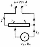
Rice. 3.
Using the formulas obtained earlier, we can write that the current flowing through the device is:
In = (U ∙ r1) / (r1 ∙ r2 + r1 ∙ r + r2 ∙ r) = (220 ∙ 7000) / (7000 ∙ 500 + 7000 ∙ 1000 + 500 ∙ 1000)= 1540000/11000000 = 1.54 / 11 = 0.14 A.
Up = Ip ∙ r = 0.14 ∙ 1000 = 14 V.
4. Calculate the voltage of the device Up, if it consumes a current Ip = 20 mA and is connected to a potentiometer divided into resistances r2 = 10 ^ 4 Ohm and r1 = 2 ∙ 10 ^ 4 Ohm (Fig. 3).
The total voltage in the voltage divider is equal to the sum of the voltage drops in its parts (through resistances r1 and r2): U = I ∙ r2 + I1 ∙ r1; U = I ∙ r2 + Up
The source current is branched at the motor contact point: I = I1 + Ip; I = Upn / r1 + In.
We substitute the value of the current I into the voltage equation:
U = (Un / r1 + In) ∙ r2 + Un;
U = Uп / r1 ∙ r2 + Iп ∙ r2 + Uп;
U = Upn ∙ (r2 / r1 +1) + In ∙ r2.
Therefore, the device voltage Upn = (U-In ∙ r2) / (r1 + r2) ∙ r1.
Substitute the numerical values: Up = (220-0.02 ∙ 10000) / 30000 ∙ 20000 = 20/3 ∙ 2 = 13.3 V.
5. A direct current source with voltage U = 120 V supplies the anode circuits of the radio receiver through a potentiometer (voltage divider), which together with the filter has a resistance of r = 10000 Ohm. The voltage U1 is removed by the resistance r2 = 8000 Ohm. Calculate the anode voltage at no load and at load current I = 0.02 A (Fig. 4).
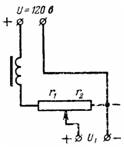
Rice. 4.
The first case is similar to example 1:
U: U1 = r: r2;
U1 = r2 / r ∙ U = 8000/10000 ∙ 120 = 96 V.
The second case is similar to example 3:
U1 = (U-I ∙ r1) / r ∙ r2;
U1 = (120-0.02 ∙ 2000) / 10000 ∙ 8000 = 64 V.
When charging, the voltage will drop from 96 to 64 V.If more voltage is needed, then the slider should be moved to the left, that is, the resistance r2 should be increased.
6. Voltages Ua and Ub are removed by the voltage divider. The total resistance of the voltage divider connected to the voltage U1 = 220 V is r = 20,000 Ohm. What is the voltage Ua in the resistance r3 = 12000 Ohm with current consumption Ia = 0.01 A and the voltage Ub in the resistance r2 + r3 = 18000 Ohm with current consumption Ib = 0.02 A (Fig. 5).
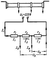
Rice. 5.
Voltage resistance r3
Ua = I3 ∙ r3;
Ua = (U -Ia ∙ (r1 + r2) -Ib ∙ r1) / r ∙ r3;
Ua = (220-0.01 ∙ 8000-0.02 ∙ 2000) / 20 000 ∙ 12000 = (220-80-40) / 20 ∙ 12 = 60 V.
The voltage Ub is equal to the sum of the voltage drop Ua across the resistance r3 and the voltage drop across the resistance r2. The voltage drop across resistance r2 is equal to I2 ∙ r2. Current I2 = Ia + I3. The current I3 can be calculated as in example 1:
I3 = (220-80-40) / 20,000 = 0.005 A;
I2 = Ia + I3 = 0.01 + 0.005 = 0.015 A.
Voltage Ub = Ua + I2 ∙ r2 = 5 + 0.015 ∙ 6000 = 150 V.
7. Calculate the combined shunt for the milliammeter so that at different positions of the switch it has the following measurement ranges: I1 = 10 mA; I2 = 30mA; I3 = 100mA. The shunt connection diagram is shown in fig. 6. Internal resistance of the device ra = 40 Ohm. Intrinsic measuring range of milliammeter 2 mA.
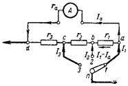
Rice. 6.
When measuring current I≤2mA, the shunt is switched off.
a) When measuring the current I = 10 mA, the switch is in position 1 and a current of 10-2 = 8 mA flows through all the shunt resistances. The voltage drop across the shunt resistance Ush and the device Ua between points d and a must be the same
Ush = Ua;
(I1-Ia) ∙ (r1 + r2 + r3) = Ia ∙ ra;
0.008 ∙ (r1 + r2 + r3) = 0.002 ∙ 40.
b) When measuring current I2 = 30 mA, the switch is in position 2. The measured current will divide at point b. At full deflection of the pointer of the device, the current Ia = 2 mA will pass through the resistance r1 and the device ra.
The rest of the current I2-Ia will pass through the resistances r2 and r3. The currents will create the same voltage drop across the two branches between points d and b:
(I2-Ia) ∙ (r2 + r3) = Ia ∙ r1 + Ia ∙ ra;
(0.03-0.002) ∙ (r2 + r3) = 0.002 ∙ (r1 + 40).
c) In a similar way, we will perform the calculation when increasing the measurement range to I3 = 100 mA. Current I3-Ia will flow through resistance r3 and current Ia through resistances r1, r2, ra. The voltage in both branches is the same: (I3-Ia) ∙ r3 = Ia ∙ r1 + Ia ∙ r2 + Ia ∙ ra;
0.098 ∙ r3 = 0.002 ∙ (r1 + r2 + 40).
We obtained three equations with three unknown values of resistances r1, r2 and r3.
We multiply all equations by 1000 and convert them:
r1 + r2 + r3 = 10;
14 ∙ (r2 + r3) -r1 = 40;
49 ∙ r3-r1-r2 = 40.
Let's add the first and third equations: 50 ∙ r3 = 50;
r3 = 50/50 = 1 ohm.
Let's add the first and second equations: 15 ∙ r2 + 15 ∙ r3 = 50;
15 ∙ r2 + 15 ∙ 1 = 50;
15 ∙ r2 = 35; r2 = 2.34 ohms.
Let's substitute the obtained results in the first equation: r1 + 35/15 + 1 = 10;
15 ∙ r1 + 35 + 15 = 150;
r1 = 100/15 = 6.66 ohms.
The correctness of the calculation can be checked by substituting the obtained resistance values into the equations.