Calculations for improving the power factor in a single-phase network
 In an AC network, there is almost always a phase shift between voltage and current, because inductances are connected to it - transformers, chokes and mainly asynchronous motors and capacitors - cables, synchronous compensators, etc.
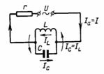
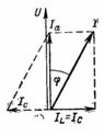
Along the chain marked with a thin line in fig. 1, the resulting current I passes with a phase shift φ relative to the voltage (Fig. 2). Current I consists of active component Ia and reactive (magnetizing) IL. There is a 90° phase shift between components Ia and IL.
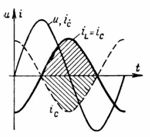
The curves of the source terminal voltage U, the active ingredient Ia and the magnetizing current IL are shown in Fig. 3.
In those parts of the period, when the current I increases, the magnetic energy of the coil field also increases. At that time, electrical energy is converted into magnetic energy. When the current decreases, the magnetic energy of the coil field is converted to electrical energy and fed back to the power grid.
In active resistance, electrical energy is converted into heat or light, and in the motor into mechanical energy. This means that the active resistance and the motor convert electrical energy into heat and, respectively, mechanical energy coil (inductance) or the capacitor (capacitor) does not consume electrical energy, because at the moment of coagulation of the magnetic and electric field it is completely returned to the power network.
Rice. 1.
Rice. 2.
Rice. 3.
The greater the inductance of the coil (see Fig. 1), the greater the current IL and the phase shift (Fig. 2). With a larger phase shift, the power factor cosφ and the active (useful) power are smaller (P = U ∙ I ∙ cosφ = S ∙ cosφ).
With the same total power (S = U ∙ I VA), which, for example, the generator gives to the network, the active power P will be smaller at a larger angle φ, i.e. at a lower power factor cosφ.
The cross-section of the winding wires must be designed for the received current I. Therefore, the desire of electrical engineers (power engineers) is to reduce the phase shift, which leads to a decrease in the received current I.
A simple way to reduce the phase shift, that is, to increase the power factor, is to connect the capacitor in parallel with the inductive resistance (Fig. 1, the circuit is circled with a bold line). The direction of the capacitive current IC is opposite to the direction of the magnetizing current of the coil IL. For a certain choice of capacitance C, the current IC = IL, that is, there will be resonance in the circuit, the circuit will behave as if there is no capacitive or inductive resistance, that is, as if there is only active resistance in the circuit.In this case, the apparent power is equal to the active power P:
S = P; U ∙ I = U ∙ Ia,
from which it follows that I = Ia, and cosφ = 1.
With equal currents IL = IC, i.e. equal resistances XL = XC = ω ∙ L = 1⁄ (ω ∙ C), cosφ = 1 and the phase shift will be compensated.
The diagram in fig. 2 shows how adding current IC to the resulting current I reverses the change. Looking at the closed circuit of L and C, we can say that the coil is connected in series with the capacitor, and the currents IC and IL flow one after the other. The capacitor, which is charged and discharged alternately, provides a magnetizing current Iμ = IL = IC in the coil, which is not consumed by the network. A capacitor is a type of AC battery to magnetize the coil and replace the grid, which reduces or eliminates the phase shift.
The diagram in fig. 3 half period shaded areas represent magnetic field energy transforming into electric field energy and vice versa.
When the capacitor is connected in parallel with the network or the motor, the resulting current I decreases to the value of the active component Ia (see Fig. 2). By connecting the capacitor in series with the coil and the power supply, compensation of the phase shift can also be achieved. The series connection is not used for cosφ compensation because it requires more capacitors than the parallel connection.
Examples 2-5 below include capacity value calculations for purely educational purposes. In practice, capacitors are ordered based not on capacitance but on reactive power.
To compensate for the reactive power of the device, measure U, I and the input power P.According to them, we determine the power factor of the device: cosφ1 = P / S = P / (U ∙ I), which should be improved to cosφ2> cosφ1.
The corresponding reactive powers along the power triangles will be Q1 = P ∙ tanφ1 and Q2 = P ∙ tanφ2.
The capacitor must compensate for the reactive power difference Q = Q1-Q2 = P ∙ (tanφ1-tanφ2).
Examples of
1. A single-phase generator in a small power plant is designed for a power S = 330 kVA at a voltage U = 220 V. What is the largest network current that the generator can provide? What active power does the generator generate with a purely active load, that is, with cosφ = 1, and with active and inductive loads, if cosφ = 0.8 and 0.5?
a) In the first case, the generator can provide the maximum current I = S / U = 330,000 /220 = 1500 A.
Active power of the generator under active load (plates, lamps, electric ovens, when there is no phase shift between U and I, i.e. at cosφ = 1)
P = U ∙ I ∙ cosφ = S ∙ cosφ = 220 ∙ 1500 ∙ 1 = 330 kW.
When cosφ = 1, the full power S of the generator is used in the form of active power P, that is, P = S.
b) In the second case, with active and inductive, i.e. mixed loads (lamps, transformers, motors), a phase shift occurs and the total current I will contain, in addition to the active component, a magnetizing current (see Fig. 2). At cosφ = 0.8, the active power and active current will be:
Ia = I ∙ cosφ = 1500 ∙ 0.8 = 1200 A;
P = U ∙ I ∙ cosφ = U ∙ Ia = 220 ∙ 1500 ∙ 0.8 = 264 kW.
At cosφ = 0.8, the generator is not loaded at full power (330 kW), although a current I = 1500 A flows through the winding and connecting wires and heats them.The mechanical power supplied to the generator shaft must not be increased, otherwise the current will increase to a dangerous value compared to that for which the winding is designed.
c) In the third case, with cosφ = 0.5, we will increase the inductive load even more compared to the active load P = U ∙ I ∙ cosφ = 220 ∙ 1500 ∙ 0.5 = 165 kW.
At cosφ = 0.5, the generator is only 50% used. The current still has a value of 1500 A, but of which only Ia = I ∙ cosφ = 1500 ∙ 0.5 = 750 A is used for useful work.
The magnetizing current component Iμ = I ∙ sinφ = 1500 ∙ 0.866 = 1299 A.
This current must be compensated by a capacitor connected in parallel to a generator or consumer so that the generator can supply 330 kW instead of 165 kW.
2. A single-phase vacuum cleaner motor has useful power P2 = 240 W, voltage U = 220 V, current I = 1.95 A, and η = 80%. It is necessary to determine the motor power factor cosφ, reactive current and the capacitance of the capacitor, which equalizes cosφ to unity.
The supplied power of the electric motor is P1 = P2 / 0.8 = 240 / 0.8 = 300 W.
Apparent power S = U ∙ I = 220 ∙ 1.95 = 429 VA.
Power factor cosφ = P1 / S = 300 / 429≈0.7.
Reactive (magnetizing) current Iр = I ∙ sinφ = 1.95 ∙ 0.71 = 1.385 A.
For cosφ to be equal to unity, the capacitor current must be equal to the magnetizing current: IC = Ip; IC = U / (1⁄ (ω ∙ C)) = U ∙ ω ∙ C = Ir.
Therefore, the value of the capacitance of the capacitor at f = 50 Hz C = Iр / (U ∙ ω) = 1.385 / (220 ∙ 2 ∙ π ∙ 50) = (1385 ∙ 10 ^ (- 6)) / 69.08 = 20 μF.
When a 20 μF capacitor is connected in parallel to the motor, the power factor (cosφ) of the motor will be 1 and only the active current Ia = I ∙ cosφ = 1.95 ∙ 0.7 = 1.365 A will be consumed by the network.
3. A single-phase asynchronous motor with useful power P2 = 2 kW operates at voltage U = 220 V and frequency 50 Hz. The motor efficiency is 80% and cosφ = 0.6. Which bank of capacitors should be connected to the motor to give cosφ1 = 0.95?
Motor input power P1 = P2 / η = 2000 / 0.8 = 2500 W.
The resulting current consumed by the motor at cosφ = 0.6 is calculated based on the total power:
S = U ∙ I = P1 / cosφ; I = P1 / (U ∙ cosφ) = 2500 / (220 ∙ 0.6) = 18.9 A.
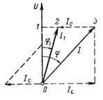
The required capacitive current IC is determined based on the circuit in Fig. 1 and diagrams in FIG. 2. The diagram in Fig.1 represents the inductive resistance of the motor winding with a capacitor connected in parallel with it. From the diagram in fig. 2 we turn to the diagram in fig. 4, where the total current I after connecting the capacitor will have a smaller offset φ1 and a value reduced to I1.
Rice. 4.
The resulting current I1 with improved cosφ1 will be: I1 = P1 / (U ∙ cosφ1) = 2500 / (220 ∙ 0.95) = 11.96 A.
In the diagram (Fig. 4), the segment 1–3 represents the value of the reactive current IL before compensation; it is perpendicular to the voltage vector U. The 0-1 segment is the active motor current.
The phase shift will decrease to the value φ1 if the magnetizing current IL decreases to the value of segment 1-2. This will happen when a capacitor is connected to the motor terminals, the direction of the current IC is opposite to the current IL and the magnitude is equal to the segment 3–2.
Its value IC = I ∙ sinφ-I1 ∙ sinφφ1.
According to the table of trigonometric functions, we find the values of the sines corresponding to cosφ = 0.6 and cosφ1 = 0.95:
IC = 18.9 ∙ 0.8-11.96 ∙ 0.31 = 15.12-3.7 = 11.42 A.
Based on the value of IC, we determine the capacity of the capacitor bank:
IC = U / (1⁄ (ω ∙ C)) = U ∙ ω ∙ C; C = IC / (U ∙ 2 ∙ π ∙ f) = 11.42 / (220 ∙ π ∙ 100) = (11420 ∙ 10 ^ (- 6)) / 69.08≈165 μF.
After connecting a battery of capacitors with a total capacity of 165 μF to the motor, the power factor will improve to cosφ1 = 0.95. In this case, the motor still consumes the magnetizing current I1sinφ1 = 3.7 A. In this case, the active current of the motor is the same in both cases: Ia = I ∙ cosφ = I1 cosφ1 = 11.35 A.
4. A power plant with power P = 500 kW operates at cosφ1 = 0.6, which must be improved to 0.9. For what reactive power should capacitors be ordered?
Reactive power at φ1 Q1 = P ∙ tanφ1 .
According to the table of trigonometric functions, cosφ1 = 0.6 corresponds to tanφ1 = 1.327. The reactive power that the plant consumes from the power plant is: Q1 = 500 ∙ 1.327 = 663.5 kvar.
After compensation with improved cosφ2 = 0.9, the plant will consume less reactive power Q2 = P ∙ tanφ2.
The improved cosφ2 = 0.9 corresponds to tanφ2 = 0.484, and the reactive power Q2 = 500 ∙ 0.484 = 242 kvar.
The capacitors must cover the reactive power difference Q = Q1-Q2 = 663.5-242 = 421.5 kvar.
The capacity of the capacitor is determined by the formula Q = Iр ∙ U = U / xC ∙ U = U ^ 2: 1 / (ω ∙ C) = U ^ 2 ∙ ω ∙ C;
C = Q: ω ∙ U ^ 2 = P ∙ (tanφ1 — tanφ2): ω ∙ U ^ 2.