Control and signaling devices for disconnectors and short circuits
 Remote control circuits are used not only to control circuit breakers but also to control disconnectors, separators, short circuits, etc.
Disconnector control and signaling devices
Consider in what equipment and what secondary connections a circuit for remote control of disconnectors with an electric motor is used. This type of actuators have a different design depending on the place of installation.
In a closed switchgear 6-10 kV, the kinematics of the actuator is usually performed in such a way that at its first 180 ° rotation, one operation is performed (for example, the disconnector is turned on). When rotating the next 180 °, another operation is performed (the disconnector is turned off).
I have disconnectors 110 and 220 kV, the direction of movement of the motor when switching on and off is opposite.
An ad hoc control circuit of the disconnector made for direct current operation is shown in Fig. 1. In such cases, an alternating current of 380/220 V can also be used.
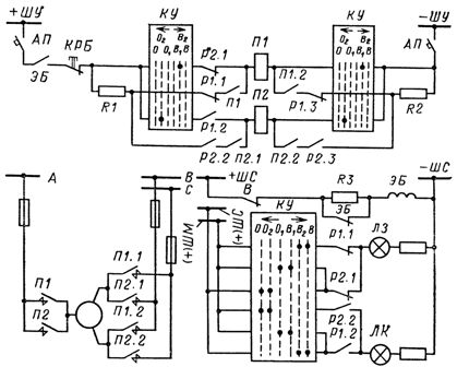
Rice. 1. Disconnector motor drive control circuit
It is typical to use a reversing starter with two windings P1 and P2. The switch on or off command is sent using the KU control switch on the control panel (or in the railway control cabinet). The starter is located in the switchgear control cabinet.
The auxiliary opening contacts of the disconnector P1.1 and P1.2 are activated at the end of the closing operation, and the closing auxiliary contacts P2.1 and P2.2 at the end of the opening operation. The blocking contact KRB is used for remote or manual control of the disconnector.
When the operation is performed manually, the KRB contact opens the remote control circuit, but at the same time opens access to manual control. When the key is turned during the whole operation, a mismatch is created between the position of the disconnector and the position of the key, and the lamp LZ (or LK), fed in this case from the flashing rails (±) of BL, lights up with a flashing light. The completion of the operation is fixed by the uniform burning of one or the other lamp.
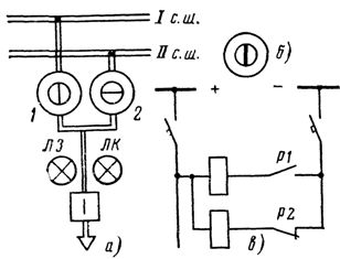
Rice. 2. Mnemonic diagram of the control panel: a — circuit element for overhead or cable line, b — position indicator, c — signal circuit, 1 and 2 — PSI devices signaling the position of disconnectors, LZ and LK — green and red position switch signaling lamp.
From the diagram you can see that the electric motor itself is powered by a three-phase AC network (busbars A, B, C). However, the supply of the electromotor drive (for example for 6-10 kV disconnectors) can also be supplied from the DC network.In addition, the circuit uses electromagnetic blocking of the EB, which prevents the production of erroneous operations with disconnectors under load. The duration of the individual operations of turning on and off the disconnectors is quite long — about 30 s.
In some cases, a PSI-type signaling device is used to signal the position of the disconnectors. Its connection diagram is shown in fig. 2.
The device has two coils. When the disconnector is turned on, its auxiliary contact is in the closed position, as a result of which power is supplied to the corresponding PSI coil, which switches the indicator to the vertical position (Fig. 2, b), when it is turned off (auxiliary contact P2 closes), to horizontal.
In the absence of current in both windings (ie, in the event of a power failure or a circuit break in the secondary circuits), the pointer is placed in an intermediate position between them, i.e. at an angle of 45 °. Thus, the PSI device installed on the control panel of the control panel also monitors the integrity of the secondary circuits coming from the switchgear to the control panel.
Control and signaling devices for separators and short circuits
At some substations connected to transit power lines 35-220 kV, instead of a switch on the high voltage side, an OD separator and a short-circuit breaker are installed (Fig. 3). They are controlled remotely.
For the OD trip separator, the SHPO drive is used, the trip spring of which is influenced by the EOO trip solenoid through the lock 3.2 and a special blocking relay for the BRO trip. The latter is connected to the short-circuit current transformer TT.
The separator is engaged manually until the opening spring OO is started. In the event of a short circuit, a SHPK drive is used for switching on the closing spring PRV, on which the switching electromagnet EVK acts through the lock 3.1. The short circuit is removed manually. In fig. 3, b and c show simplified OD and SC control and signaling schemes.
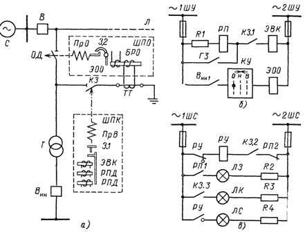
Rice. 3. Control circuits of separators and short circuits: a — single-transformer substation circuit, b — control circuit, c — signaling circuit.
Fig. 3, b, it can be seen that when closed on the lower side of the Vnn switch, the auxiliary contact BHH1 will close. With the KU key, when you turn it to the left, the OD splitter can be remotely disconnected from the EOO device. The short circuit is not a working device and is therefore not controlled by the KU key. Under normal conditions, the coil of the electromagnet EVK moves with a small current, insufficient for its operation. In this case, the contact RP1 is closed, the green lamp LZ lights up.
When any protection is triggered on the transformer T, for example the gas protection with internal faults of the transformer, the resistor R1 and the coil of the relay RP are short-circuited by its contact GZ, the current in the coil EVK increases significantly, as a result of which the electromagnet The EVK is triggered and the short circuit is activated, creating an artificial short circuit. The red LC lamp lights up. On the transit line, the protection cuts off the short circuit with switch B.
In the event of a violation of the integrity of the EVK circuit, the LS signal lamp lights up. The short-circuit drive may also have built-in current relays with direct-acting RPDs.After tripping of the short-circuit breaker, line switch B, OD separator are automatically turned off, then by means of automatic line reclosing, switch B is turned on again, and thus power to row L is restored.