Busbar constructions of switchgear
 Busbars are bare, relatively massive current-carrying conductors with a rectangular, round or profiled cross-section. In the premises of a closed switchgear, all branches from the busbars and connections to the devices are also made with bare conductors forming a busbar.
Shinny are the central and most critical part of the switchgear, as they receive electricity from all station generators (or substation transformers) and all outgoing lines are connected to them.
In closed switchgear up to and including 35 kV, the busbars are made of rectangular aluminum strips. Steel tires are used in low-power electrical installations at load currents that do not exceed 300-400 A.
It should be noted that rectangular (flat) wires are more economical than round wires. With the same cross-sectional area, a rectangular tire has a larger lateral cooling surface than a round tire.
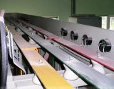
In the distribution room, tires are mounted on special bus racks or equipment cage frames. Busbars are placed on the supporting porcelain insulators on the edge or flat and fixed with busbar holders.
There are many different ways to mount tires. Each of them has its advantages and disadvantages.
Cooling conditions are better for ribbed tires than for flat tires. In the first case, the heat transfer coefficient is 10-15% higher than in the second, and this is taken into account when determining the permissible current load (PUE). Tires facing their neighbors with their narrow side (rib) have greater mechanical stability.
In order to allow the tires to move along their small pattern when the temperature is extended, the tire is fixed tightly in the middle of the section and loosely in the distance. In addition, for long bus lengths, compensators are installed to accommodate temperature expansion. The two busbars are interconnected using a flexible bundle of thin copper or aluminum strips. The ends of the busbar strips are not firmly attached to the supporting insulator, but a sliding attachment through the longitudinal oval holes.
To eliminate temperature stresses, the busbars are in some cases connected to fixed devices (clamps) using flexible packages that are built at the ends of rigid busbars.
The largest single strip copper and aluminum busbar sizes used are 120×10 mm.
For high current loads (for copper busbars over 2650 A and for aluminum - 2070 A) multi-band busbars are used - packages of two or less often three bands per phase; the normal distance between the strips in the package is taken equal to the thickness of one strip (b).
The proximity of strips from the same package to each other causes an uneven distribution of current between them: a large load falls on the end strips of the package and less on the middle ones. For example, in a three-strip package, 40% each flows in the outer strips and only 20% of the total phase current in the middle. This phenomenon, which is analogous to the peeling phenomenon in a single conductor, makes it impractical to use more than three AC buses.
With operating currents exceeding those permitted for two-lane buses, it is most recommended to use tires with a profile (channels), which enable better use of the conductive material and achieve high mechanical strength.
Power installations currently use a package of two channels per phase, which approximates in shape and kp to a hollow square. The largest channel size with a wall of 250 mm and a thickness of 12.5 mm with two channels in the package allows the transmission of a current of 12,500 A for copper and 10,800 A for aluminum.
The tires and all busbars of a closed switchgear are painted with enamel paints in identifying colors, enabling service personnel to easily recognize live parts connected to certain phases and circuits.
In addition, the paint protects the tires from oxidation and improves heat transfer from the surface. The increase in allowable current from busbar color is 15-17% for copper and 25-28% for aluminum busbars.
The following colors are used for buses with different phases: three-phase current: phase A — yellow, phase B — green, phase C — red; zero busbars: with ungrounded neutral — white, with grounded neutral, as well as grounding wires — black; DC current: positive rail is red, negative rail is blue.
The busbar of the open switchgears can be implemented with flexible wires or rigid rubbers. At voltages 35, 110 kV and more, in order to increase the corona voltage and reduce corona losses, only round wires are used.
In most open switchgear, the busbar is made of stranded steel-aluminum conductors of the same design as power lines.
Copper bus conductors are used only in cases where the open switchgear is located close (about 1.5 km) to the shores of salty seas or chemical plants, whose active vapors and entrainment can cause rapid corrosion of aluminum conductors. In some cases, open switchgear uses a rigid busbar made of steel or aluminum tubes fixed on support insulators.
Cross-sections of tires and other current-carrying conductors can be calculated based on the value of operating currents and allowable temperatures based on heating conditions.
As for the busbars used in switchgear, their cross-sections are standardized and tables of permissible continuous current loads have been drawn up for them. Therefore, in practice there is no need to calculate by formulas, but it is enough to make a choice according to the tables.
Tables of permissible continuous current loads on bare busbars and conductors are calculated and verified experimentally; when compiling them, a permissible heating temperature of 70 ° C at an ambient temperature of + 25 ° C was assumed.
Such tables for standard cross-sections of tires and wires of basic conducting materials and certain profiles (rectangular, tubular, channel, hollow square, etc.) are given in PUE and reference books.
For rectangular busbars, the tabulated current loads are compiled when installed at the edge; therefore, when the tires are flat, the loads should be reduced by 5% for tires with tread widths up to 60mm and by 8% for tires over 60mm. In cases where the average ambient temperature differs from the standard (+ 25 ° C), the permissible tire loads obtained from the tables must be recalculated according to the following approximate formula:
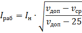
where IN is the allowable load taken from the tables.
The cross-section of the wires must be checked against the economic current density.
The economic cross-section of wires or buses qEC is called such a cross-section where the total annual cost, determined by capital costs and operating costs, turns out to be the smallest.
The economic cross-section of wires and busbars is obtained by dividing the maximum load current in normal mode by the electric current density:

The resulting cross-section according to the economic condition is rounded to the nearest standard and checked for the long-term permissible load current. It should be noted that the RU busbars for all voltages are not selected according to the economic current density, because the economic sections at high currents are equal to or smaller than the sections selected for heating.
In addition, RU tires are checked for thermal and electrodynamic stability in the event of a short circuit, and at 110 kV and above, also for corona.
Thus, wires of any purpose must meet the requirements for the maximum permissible heating, taking into account not only normal, but also emergency modes.
If the conductor cross-section determined by economic and continuous load conditions is not equal to the cross-section required for other emergency conditions (thermal and dynamic stability during short-circuit), then a larger cross-section should be is assumed to meet all conditions.
It should also be noted that when installing tires with large sections, it is necessary to ensure the lowest additional losses from the surface effect and the proximity effect and the best cooling conditions. This can be achieved by reducing the number of strips in the package and their correct spatial and mutual arrangement, rational design of the package, use of profile tires — trough, hollow, etc.
When using steel tires, the determination of the permissible current value is carried out in a slightly different way.
In steel tires, due to the surface effect, there is a significant shift of the current to the surface of the conductor, the penetration depth does not exceed 1.5-1.8 mm.
Studies have found that the allowable load of AC steel busbars practically depends on the cross-sectional perimeter of the busbar, not on the area of this cross-section.
Based on these studies, the following method was adopted for the calculation of AC steel busbars:
1. First, determine the bus load current (for a bus with one side not exceeding 300-400 A) and find the linear current density:

where In — load current, A; p is the cross-sectional perimeter of the tire, mm.
The linear current density depends on the allowable superheat temperature of the steel bus above the ambient temperature. This dependency is defined by the following expression:
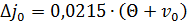
It was found that for bolted joints of steel tires, the value of Θ should not exceed 40 ° C, and for welded joints it can be increased to 55 ° C.
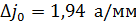
If we take the ambient temperature v0 — 35 °, then the linear current density for bolted connections will be equal to

and for welded joints
2. Based on these data, we determine the value of the required perimeter of the cross-section of the tire:

On the perimeter of the tires, having a set of tires, you can easily choose the required size of standard steel strips, observing the condition
where h is the height of the tire, mm; b — tire thickness, mm.
The steel tire calculation above is for single tread tires.
For high load currents bundles of several steel rails can be used. In this case, the perimeter of the cross-section of one strip of the tire included in the package is selected subject to the following conditions:
• for two-way buses
• for three-way buses

To simplify the calculations, you can use the diagram of the dependence of the perimeter p of the bus cross section on the load current IN.