Schemes and groups of connections of transformer windings
Connection diagrams of windings of three-phase transformers
 Three-phase transformer there are two three-phase windings — high (HV) and low (LV) voltage, each of which includes three phase windings, or phases. Thus, a three-phase transformer has six independent phase windings and 12 terminals with corresponding terminals, and the initial terminals of the winding phases with a higher voltage are indicated by the letters A, B, C, final conclusions - x, Y, Z, and for similar conclusions the following designations are used on the phases of the low-voltage winding: a, b, ° C, x, y, z.
Each of the three-phase transformer windings—primary and secondary—can be connected in three different ways, namely:
- star;
- triangle;
- zig-zag.
In most cases, the windings of three-phase transformers are connected either in star or delta (Fig. 1).
The choice of the connection scheme depends on the operating conditions of the transformer.For example, in networks with a voltage of 35 kV and more, it is more profitable to connect the windings to a star and ground the zero point, since in this case the voltage on the wires of the transmission line will be in V3 times less than linear, which leads to reduce the cost of insulation.
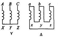
Fig. 1
It is profitable to build lighting networks for high voltage, but incandescent lamps with a high nominal voltage have low luminous efficiency. That is why it is recommended to power them from a reduced voltage. In these cases, it is also advantageous to connect the transformer windings in a star (Y), including lamps with phase voltage.
On the other hand, from the point of view of the operating conditions of the transformer itself, it is advisable to connect one of its windings in a delta.
Phase transformation factor three-phase transformer is found as the ratio of the phase voltages at no-load:
nf = Ufvnh / Ufnnh,
and the linear transformation coefficient, depending on the phase transformation coefficient and the type of connection of the phase windings of the higher and lower voltage of the transformer, according to the formula:
nl = Ulvnh / Ulnnh.
If the connections of the phase windings are made according to the «star-star» or «delta-delta» schemes, then both transformation ratios are the same, i.e. nf = nl.
When connecting the phases of the windings of the transformer according to the "star-delta" scheme — nl = nfV3, and according to the "delta-star" scheme — nl = ne/V3
Groups of connections of transformer windings
The group of connections of the transformer windings characterizes the relative orientation of the voltages of the primary and secondary windings. The change in the mutual orientation of these voltages is carried out by correspondingly re-marking the beginning and ends of the windings.
The standard designations for the start and end of the high and low voltage windings are shown in fig.
Let us first consider the effect of marking on the phase of the secondary voltage with respect to the primary, using an example single phase transformer (Fig. 2 a).
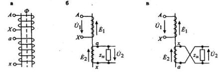
Fig. 2
Both coils are located on the same rod and have the same winding direction. We will consider the top terminals as the start and the bottom terminals as the ends of the coils. Then the EMF Ё1 and E2 will coincide in phase and, accordingly, the network voltage U1 and the voltage in the load U2 will coincide (Fig. 2 b). If we now assume the reverse marking of the terminals in the secondary winding (Fig. 2 c), then with respect to the load EMF E2 changes the phase by 180 °. Therefore, the phase of the voltage U2 changes by 180 °.
Thus, in single-phase transformers, two groups of connections are possible, corresponding to shear angles of 0 and 180 °. In practice, a clock is used for convenience when defining groups. The voltage of the primary winding U1 is depicted by the minute hand, which is permanently set to 12, and the hour hand occupies different positions depending on the offset angle between U1 and U2. An offset of 0 ° corresponds to group 0, and an offset of 180 ° to group 6 (Fig. 3).
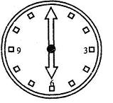
Fig. 3
In three-phase transformers, 12 different groups of winding connections can be obtained. Let's look at some examples.
Let the windings of the transformer be connected according to the scheme Y / Y (Fig. 4).The coils located on one rod will be placed one under the other.
The brackets A and a are connected to align the potential diagrams. Let us set the position of the voltage vectors of the primary winding by the triangle ABC. The position of the voltage vectors of the secondary winding will depend on the marking of the terminals. To mark fig. 4a, the EMF of the corresponding phases of the primary and secondary windings match, therefore the line and phase voltages of the primary and secondary windings will match (Fig. 4, b). The chain has a Y / Y group — O.
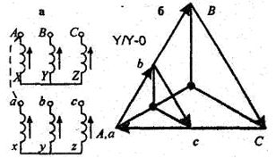
Rice. 4
Let's change the marking of the terminals of the secondary winding to the opposite one (Fig. 5. a). When re-marking the ends and the beginning of the secondary winding, the phase of the EMF changes by 180 °. Hence the group number changes to 6. This scheme has Y / Y group — b.
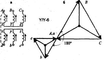
Rice. 5
In fig. 6 shows a diagram in which, compared to the diagram of FIG. 4, a circular re-marking of the terminals of the secondary winding is made. In this case, the phases of the corresponding EMF of the secondary winding are shifted by 120 ° and therefore the group number changes to 4.
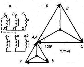
Rice. 6
Rice. 7
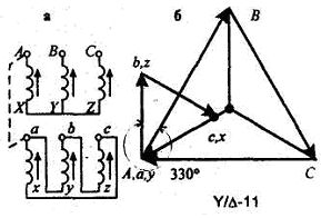
Y / Y connection diagrams allow to obtain even group numbers, when the windings are connected according to the "star-delta" scheme, the group numbers are odd. As an example, consider the circuit shown in Fig. 7.
In this circuit, the phase emf of the secondary winding coincides with the linear ones, so that the triangle abc is rotated 30 ° counterclockwise with respect to the triangle ABC. But since the angle between the line voltages of the primary and secondary windings is counted clockwise, the group will have the number 11.
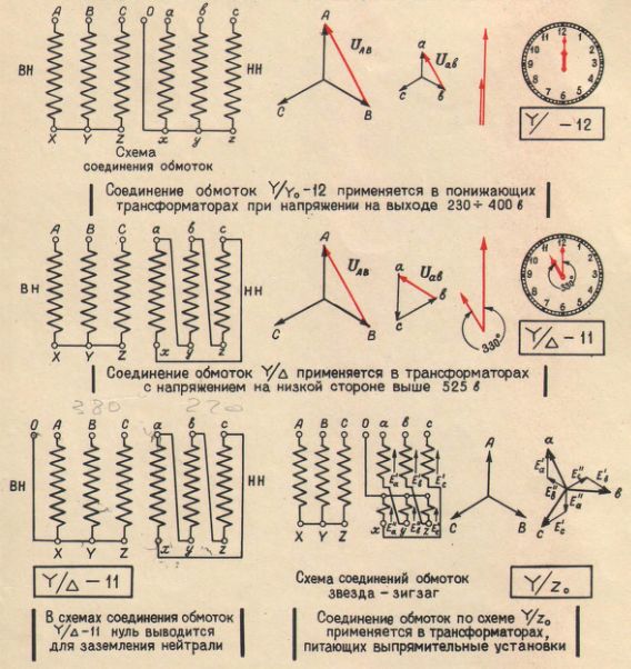
Of the twelve possible groups of winding connections of three-phase transformers, two are standardized: «star-star»-0 and «star-delta»-11. They are, as a rule, used in practice.
The "star-star with neutral" schemes are mainly used for consumer transformers with a voltage of 6 — 10 / 0.4 kV. The zero point makes it possible to obtain a voltage of 380/220 or 220/127 V, which is convenient for the simultaneous connection of both three-phase and single-phase electricity receivers (electric motors and incandescent lamps).
The «star-delta» schemes are used for high-voltage transformers, connecting the 35 kV winding in star and 6 or 10 kV in delta. Zero star is used in high voltage systems with grounded neutral.
Groups for connecting windings of three-phase transformers: