How high voltage disconnectors are arranged and work
 High Voltage Devices: How Disconnectors Are Arranged and Work Among high voltage electrical equipment, various switching devices are used. One of their groups is called "Disconnectors".
Appointment
These structures are used to create a break in the electrical circuit, which not only turns off the voltage supply, but must also be visually visible.
The fact is that throughout the long history of the exploitation of electricity, traditions have developed for its safe use. Power interruptions through load breakers with sophisticated technical devices are hidden from observation. In the event of accidents, the voltage remains in the area designated for decommissioning. This is very dangerous and is a direct prerequisite for electric shock or damage to electrical equipment.
For these reasons, disconnectors are installed in the high-voltage circuit in series with the switches and, as a rule, after them, to ensure the safety of operation.
To understand this process, we will present a part of the electrical circuit when electricity from the source of transformer substation No. 1 is transmitted through a power line divided into 5 working sections to substations No. 2 and No. 3.
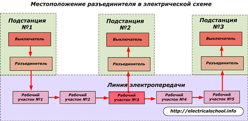
Let's assume that in section No. 3 (marked in red) it is necessary to carry out technical work requiring, according to safety conditions, stress relief.
To do this, you will need to turn off the power switches:
-
power substation No. 1;
-
consuming substations No. 2 and No. 3, which are in operation on the lower voltage side and will generate electricity to the line, including section No. 3, due to the reverse transformation effect.
In the event of a malfunction of any of the switches or an error or their spontaneous unauthorized switching on, the voltage will appear on the working section No. 3, and this is unacceptable.
Therefore, a disconnector is installed after each switch in the electrical circuit, which additionally creates a safe and visible break in the circuit.
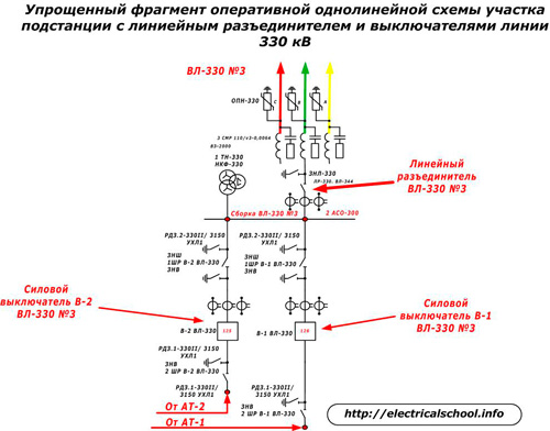
The above picture is a simple one-line design. In practice, however, high voltage power lines use a minimum of three phases. A more accurate diagram for our case of preparation of work site No. 3 for maintenance will be as follows.

On it, each phase «A», «B», «C» of the power line is shown in its own color: yellow, green and red. At all substations it is disconnected first by its own switch and then by the disconnector. Only then is each phase of the power line for site No. 3 grounded.
In this figure, the issue of grounding is not shown completely, but only to demonstrate the need for its implementation.
The location of the disconnector in the circuit determines its simplified design compared to the circuit breaker. This is due to the fact that the switch must reliably interrupt the electricity passing through it during normal operation and emergency short-circuit currents of huge magnitudes that can occur at an unforeseen moment in time anywhere in the section of the circuit protected by the switch.
These processes are very complex. They are related to the ionization of the environment and the occurrence of a powerful electric arc that can burn the contacts. To prevent this phenomenon, various technical solutions are used, based on the use of carriers with insulating properties. They fill the working area of the circuit breaker where the circuit is broken.
The second direction of dealing with the arc is to ensure the maximum speed of the trigger mechanism. Its operating time is comparable to an explosion and occurs in approximately two periods of oscillation of the harmonic of the sinusoidal current.
The same time is required for modern protections with automatic means of detecting a fault in the circuit and sending a command to the breaker drive.
Therefore, the emergency shutdown time through protection and automation is about 0.04 sec.
For disconnectors, such complex devices are not needed. They are designed to be switched off by the operator's hand or electric motors without haste. Since the disconnectors are installed after the switches, they only operate after the voltage is removed, when there can be no arcing.
The location of the disconnector and circuit breaker can be seen on a fragment of the operating diagram of the dispatcher.
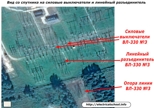
This is what the picture of the location of this substation looks like, transmitted by the satellite.
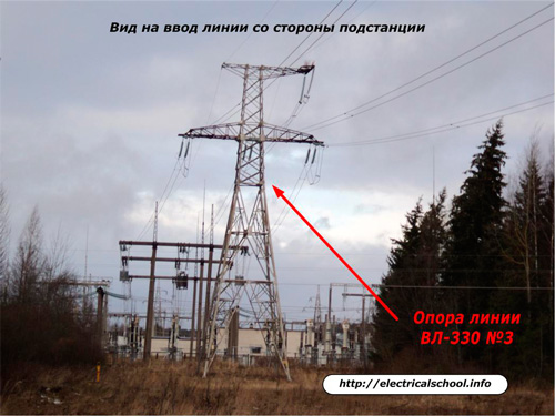
View of the same area from the ground from the side of the leading support.
Therefore, disconnectors create a visible break in the electrical circuit for its safe maintenance after the switch turns off the voltage... This is their main purpose.
Disconnector design
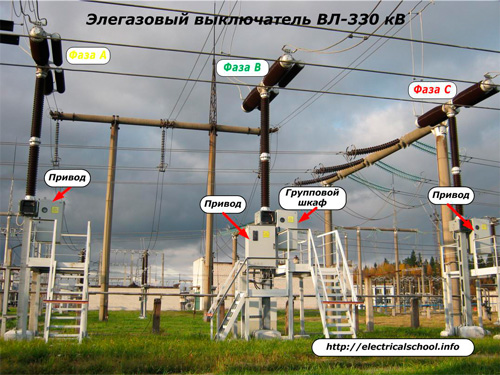
The device of a high-voltage disconnector is quite complex, but at the same time it is much simpler than that of a power switch of the same voltage. Let's look at examples of their implementation for 330 kV equipment.
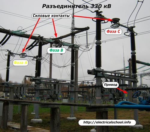
The only currents such disconnectors trip are possible capacitive discharges from induced voltages. The power contacts of the disconnectors are designed to interrupt their power supply. In working condition, the maximum load current passes through them.
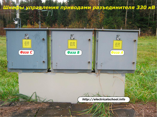
Drive control cabinets are designed to control each phase of the disconnector individually or in combination.
If you look carefully at the above pictures, you will see that the switching contacts of the switch and the disconnector are located at a considerable height. This is for safety reasons for the rest of the equipment and service personnel.
In 110 kV outdoor switchgear, the safe height of the disconnector is less.
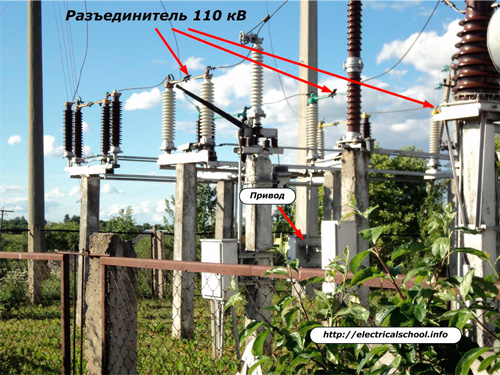
So it's better to maintain them, easier and cheaper to install. However, this requires special attention from operating personnel under the commissioned disconnector. In practice, there were cases when workers in wet weather raised their hair, reducing the safe distance to electrical equipment and falling under a voltage of 110 kV.
This once again confirms that safety measures must not only be well known, but also impeccably executed.
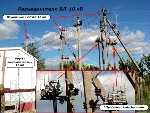
The location of 10 kV overhead transmission line disconnectors on poles near the indoor switchgear with substation power switches is shown in the photo.
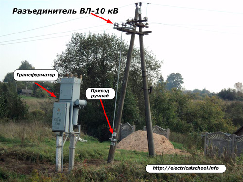
The following picture shows how to operate the 10 kV line disconnector using a manual drive. The power transformer is nearby.
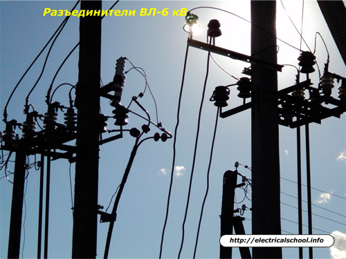
Disconnectors for 6 kV overhead lines have the same device as for 10 kV lines.
All photos show that each disconnector consists of the following structural elements:
-
power frame placed at a safe height;
-
support insulators firmly mounted on the frame at the ends of the gap formed for each phase;
-
a contact system that ensures reliable passage of the rated current of the line and disconnects the voltage supply in the open state to the section intended for service;
-
knife motion control systems.
For disconnectors used for circuits with a voltage of 110 kV and above, the contact system is made of two movable half-knives that are bent in opposite directions. In other designs, a movable knife is more often used, which is inserted into a fixed contact.
Disconnectors are classified according to:
-
the number of poles;
-
the nature of the installation (indoor or outdoor);
-
the type of movement of the knife to create the chain break (rotary, cutting or rocking);
-
control methods: manually with an operating isolation rod or lever system, or automatically by electric motors (hydraulics and even pneumatics can be used) with a control system.
All operations with disconnectors in the work scheme are classified as dangerous work, they are carried out only by trained and trained personnel using specially designed forms under the direct control of the dispatcher.
Interlocking disconnectors
A feature of high-voltage disconnectors is that together with them, on the same platform, grounding knives are often located on both sides of the created gap. It is convenient to manipulate them for operating personnel who perform switching in power circuits.
When switching on, it is important to correctly observe the sequence of applying / removing earthing and switching on / off the disconnector. The circuit breaker must not be turned on while the grounding is installed on both sides of the disconnector. This will cause a short circuit.
You also cannot force ground when the disconnector is on and voltage is applied to the circuit, which will also create a short circuit.
In order to prevent wrong situations during switching, technical blocking of the actions of the service personnel is used with stationary grounders, disconnectors and switches. She can be:
-
purely mechanical;
-
electric (based on the use of an electromagnetic lock);
-
combined.
The lock designs are different. Their complexity and reliability increase as the voltage used in the primary loop increases.
To control electrical types of interlocks, additional contacts used in secondary circuits are mounted on the rotating shafts of the contact vanes. These are called block contacts KSA. They completely repeat the position of the disconnector, at the same time they close or open.To extend the capabilities of control circuits, protections and automation of switches and lines, these block contacts are designed with both normally open and closed positions.
A similar block of contacts is also fitted on the drives of stationary earthing knives and load break switches.

Electromagnetic blocking control circuits are based on the principle of creating series and parallel circuits of electric circuits from the contacts of the repeaters of the position of the main equipment: switches, disconnectors, grounding knives.
When the position of one of these switching devices is changed by the service personnel, their secondary contacts, assembled in a certain logic scheme, are switched accordingly. If the safety requirements are violated, then electromagnetic blocking prohibits further actions with power equipment.
In this case, it is necessary to understand the correctness of the actions performed and to look for the mistake made.
Interlocking circuits for substation disconnectors are powered by dedicated DC voltage sources.
Mandatory requirements for disconnectors:
-
providing a visible gap;
-
structural resistance to dynamic and thermal effects;
-
reliability of insulation in all weather conditions;
-
clarity of work in case of deterioration of working conditions during rain, snowfall, ice formations;
-
simplicity of design, providing ease of use and maintenance.
For more details on the operating characteristics of disconnectors, see this article.