Connection diagram of a three-phase electricity meter using measuring transformers
We will consider the connection diagram of a three-phase meter, using the example of reading electrical energy carried out on overhead high-voltage power lines.
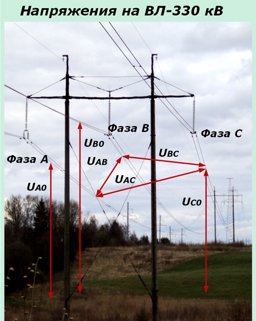
The overhead line shown in the photo has a voltage Uav, Uvs, Usa equal to 330 kV and a phase-to-ground voltage of 330 / √3. It is quite clear that direct connection of such circuits to an electricity meter cannot be carried out. It is necessary to use an intermediate product step-down voltage transformers.
You will also need to consider the loads transmitted on such lines. For their reading, it is necessary to use intermediate current transformers.
Design characteristics of three-phase electricity meters for connection by means of measuring transformers
According to the principle of operation, measuring devices for indirect connection have no particular differences from other models. They can only differ:
-
the nominal values of the measured passing currents and supply voltages;
-
power calculation algorithm, taking into account coefficients for recalculation of values;
-
information shown on the display.
This means that any meter with a direct connection can be integrated via measuring transformers into the measuring circuit (if the input parameters match) and with the help of the conversion factors the energy consumption can be measured.
This method can be used in a 0.4 kV network, taking into account the increased loads through step-down CTs with a secondary current of 5 amps.
Voltage measurement transformers are used to connect a high voltage energy meter, using a 100 volt line circuit in the secondary circuit to connect to the meter. This value is taken as a basis for all electrical installations above 1 kilovolt.
The current-measuring elements of high-voltage meters are designed to be connected to currents corresponding to the secondary circuits of the measuring transformers:
-
5 A when working in circuits up to and including 110 kV;
-
1 A — 220 kV and more.
The external view of one of the most common electricity meters of the Gran-Electro SS-301 series, designed to work in electricity metering schemes with a voltage of 110 kV, is shown in the photo.
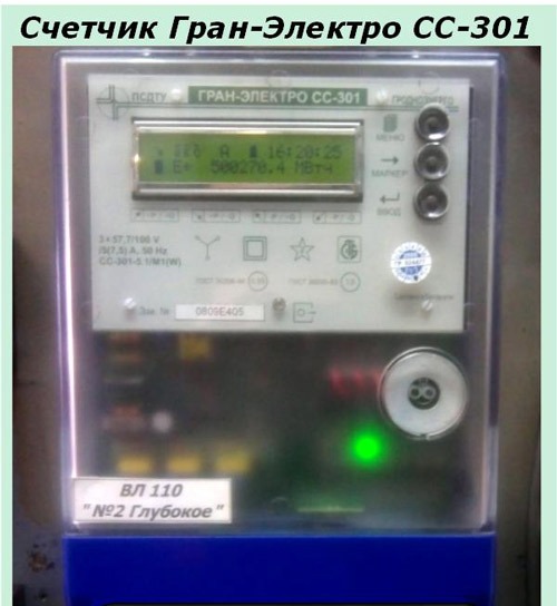
In this design, all the terminals shown in the above connection diagram of a three-phase meter are available for the installation of electrical circuits divided into sections:
-
current;
-
voltage.
Meter and CT circuits
They pass phase by phase through terminals 1-3, 4-6, 7-9, as shown in the fragment of the main diagram of the measuring circuits highlighted in white.The power for each phase of the meter is supplied by the corresponding secondary winding measuring current transformer 1TT assembled according to the scheme of a full star.
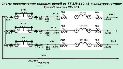
To enable you to quickly take the SS-301 meter out of service for maintenance, replacement and inspection, 7BI test block contacts are provided. When installed, the current circuits of the meter are reliably connected to the secondary circuits of the measuring transformers. If the device is removed, the meter is taken out of service and the current circuits of the CT remain closed due to the special design of the contacts.
Voltage measurement and VT circuits
The voltage of each phase is applied to terminals 2, 5, 8. The operating zero is applied to terminal 10 and removed from — 11.
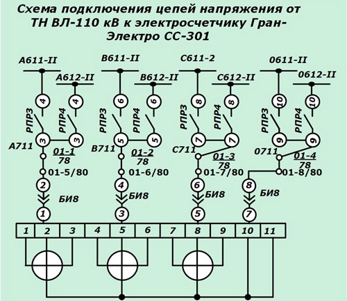
In high-voltage substations, the power of the high-voltage line is often not from one source, but from several. For this purpose, not one, but two or three power transformers / autotransformers are installed on the external switchgear, from which sections and bus power supply systems with their own voltage measuring transformers are created.
The relay contacts of the RPR repeaters are used for the simultaneous switching of the power supply of the voltage circuits together with the power equipment. In the figure, they are represented by the contacts of the relays RPR3 and RPR4, connecting phases 611-II and 612-II to their contacts to the meter.
To quickly remove the meter from work on voltage circuits, a BI8 test block is provided, the cover of which is removed to disconnect the voltage and inserted for power.