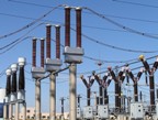
Measurement of high currents and high voltages
 Measurement of direct currents up to 6000 I is usually produced using tools of a magnetoelectric system with shunts.
High current shunts become bulky, heavy and expensive, for example a 75ShS 6000 A shunt weighs 24 kg. In addition, the use of shunts for high currents does not provide sufficient accuracy and the power losses in them are large, for example, in the above-mentioned shunt at a nominal voltage of 75 mV, the power loss is 6000 A x 0.075 V = 450 W. Therefore, for measuring large constant currents, constant current transformers are used, which are manufactured for rated primary currents from 7.5 to 70 kA with a secondary current of 5 A.
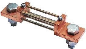 Rice. 1. Shunt B6 — rated current 1A — 15kA — voltage drop 100mV
As in alternating current circuits, the primary winding is connected to the measured current circuit (in the wire section), while the secondary windings are connected to a sinusoidal voltage source in series with the load. An EMF is induced in them, the value of which depends on the primary current.The secondary current is proportional to the primary current if the load resistance is much less than the inductive resistance of the windings.
The schematic of the DC transformer is shown in Fig. 2.
A DC transformer consists of two identical closed cores, each of which has two windings superimposed on each other. The cores are made of permaloid.
The measured direct current flows through the primary windings connected in series. Two secondary windings connected in series (or parallel) are connected through a rectifier to an AC power source.
The secondary windings are connected so that during the first half-cycle of alternating current i2 secondary n. p. i2w2 in the first core has the opposite direction with respect to the primary n. p. i1w21 and in the second core the directions of the primary and secondary n. v. matches. In the second half-period, on the contrary, in the first core of the n direction. v. coincide, and in the second they will have opposite directions.
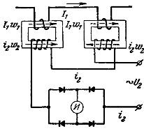
Rice. 2. Schematic of a DC measuring transformer
In the presence of a constant measured current in the primary circuit of the current transformer, an alternating current with a rectangular shape of the curve will flow in the secondary circuit, and a direct current will flow in the diagonal of the bridge rectifier to which the measuring mechanism is connected. The change in the magnitude of the measured current will lead to a change in the primary N. with F =i1wl.
By measuring the secondary current and multiplying it by the real one Yes every transformation coefficient, we get the actual value of the primary current.
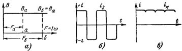
Rice. 3. Characteristics of the current transformer: a — magnetization curve; b — current curve in the secondary circuit; c — current curve in the glucometer.
Measurement of large alternating currents, as a rule, is carried out by ammeters of electromagnetic, ferro-dynamic, electrodynamic systems, which are switched on by measuring current transformers, which are produced for rated primary currents up to 25 kA.
Used in some cases, the inclusion of ammeters directly in the section of wires or busbars (without current transformers) at circuit voltages above 500 V should be done in such a way as to ensure the safety of service and the convenience of observing the readings of the device .Ammeters in such cases are often isolated from ground by mounting them on insulators.
In high-voltage circuits, regardless of the type of current and frequency, we must aim to include an ammeter in a section of the circuit at a potential equal to or close to the ground potential, because otherwise there is a danger to the experimenter and maintenance personnel, they may additional errors arise from the electric field and unfavorable conditions for the operation of the insulation of the device, which in this case must be consistent with the operating voltage of the measured circuit.
In high-voltage DC circuits, the voltage can be measured:
1) voltmeters of the magnetoelectric system, which are manufactured for nominal voltage up to 6 kV,
2) voltmeters of the electrostatic system, which are produced for a nominal voltage of up to 100 kV,
3) using DC voltage measuring transformers.
In fig. 4 is a diagram of a DC voltage measurement transformer. The primary windings of the transformer connected in series with the additional resistance are connected to the measured voltage.The secondary windings connected in parallel are connected through a rectifier to an AC supply. A measuring mechanism is included in the diagonal of the rectifier circuit.
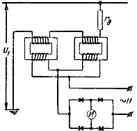
Rice. 4. Schematic of a transformer for measuring DC voltage
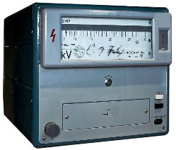
Rice. 5. Electrostatic kilovoltmeter
In high-voltage AC circuits, voltage measurement is usually done with voltmeters rated at 100 V connected through voltage-measuring transformers. In this case, on the one hand, the difficulties of making devices directly for high voltage disappear, on the other hand, the danger to service personnel when working with measuring devices connected directly to high voltage wires is eliminated.
In high voltage technology, special electrostatic voltmeters, spark plugs and electronic oscilloscopes are often used to measure high voltage. The last two of these devices are primarily used to measure voltage pulses.