Light barriers of high obstacles for industrial enterprises
 Light barriers of high-rise buildings, which are an obstacle to the movement of aircraft, are implemented in accordance with the "Manuals for Airport Service in Civil Aviation" (NAS GA-86) in order to ensure the safety of flights at night and in poor visibility ( low clouds, fog, precipitation).
Obstacles are divided into airport and linear. Aerodrome obstacles are located on the territory near the airport, i.e. on the ground in the immediate vicinity of the airport, over which aircraft are maneuvered in the airspace. For airport obstacles, a light barrier is provided at each height.
Linear obstacles include tall buildings located outside the airport area, in the airways or on the ground. The height of linear obstacles where a light barrier is required depends on the location of the obstacles. (This provision does not apply to obstacles over 100 m high, which must be provided with a light strip in all cases.)
If linear obstacles are located on the territory of air approach lanes (VFR), where it is climbed after take-off and descent during the approach, the light barrier is arranged for obstacles: at any height — at a distance from the take-off strip (OP) up to 1 km ; with a height of more than 10 m — at a distance from the OP from 1 to 4 km; with a height of 50 m and more — at a distance from the OP of 4 km to the end of the TIR.
Light barriers, regardless of height, must have the following linear obstacles:
• Restrictions on obstacles that rise above established surfaces;
• objects of departments for internal affairs, radio navigation and landing.
 Since electrical designers do not have information about how obstacles are located in relation to aerodromes, airways, airways, airstrips, the need for light barriers at certain sites and their distribution to aerodrome or linear obstacles must be determined by the tasks of the general designer, prepared based on the requirements of the regional departments of the Ministry of Civil Aviation and the Ministry of Defense.
In the construction part of the project for high-rise buildings, access to light barriers (stairs, platforms with fences, etc.).
There should be obstacles light barriers at the very top (point) and below every 45 m... As a rule, the distances between the intermediate levels should be the same. It should be noted that the height of any obstacle should be considered its height relative to the absolute elevation of the terrain on which it is located. In the case when the structure stands on a separate hill that stands out from the general flat relief, the height of the obstacle is considered from the foot of the hill.
For linear obstacles located in built-up industrial zones, a light barrier is installed from the upper point to a height of 45 m above the average height of the building.
Long obstacles (Fig. 1) or a group of them located close to each other must have a light barrier at the upper points along a common outer contour with an interval of no more than 45 m. The highest obstacles included in the upper contour receive additional light barrier. For elongated obstacles in the form of horizontal networks (overhead power lines, antennas, etc.), suspended between the masts, the light fence is arranged on the masts (supports) regardless of the distance between them.
At the upper points of obstacles, and for extended obstacles and at the upper corner points, two lights (main and backup) are installed, working simultaneously or one at a time, if there is a device for automatically turning on the backup fire when the main one fails. If in any direction the light of the light barrier is obscured by another (nearby) object, then this object must be provided with additional light. In this case, the fire covered by the object, if it does not show an obstacle, is not installed.
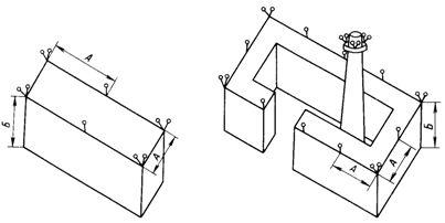
Rice. 1. Example of placing light barriers on an extended high barrier: A — no more than 45 m; B — 45 m and more... Rice. 2. Example of placement of light protective lights along the general contour of a group of tall buildings: A — no more than 45 m; In — 45 m and more

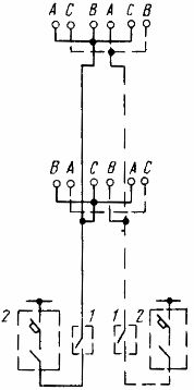
Rice. 3. Example of a light barrier on a chimney: H — no more than 45 m; A, B, C — mains phases
On chimneys, the upper lights are placed 1.5-3 m below the edge of the pipe.The number and location of obstacle lights at each stack or mast level shall be such that at least two obstacle lights are visible from each direction of flight. Examples of placement of obstacle lights on some obstacles are shown in fig. 2 and 3.
Light barriers are used as obstacle lights of the ZOL-2 or ZOL-2M types with an incandescent lamp SGA220-130 (with a 1F-S34-1 base), as well as lights of the ESP-90-1 type.
Due to the lack of explosion-proof obstacle lights, before the development of such lighting devices, light barriers in hazardous areas can be made with lamps of the type N4BN-150) with 100 W LN, coated with red paint on the inside surface of the protective glass of the lighting body.
Obstacle lights mounted with glass up at a height of approximately 1.5m from service platform level. ZOL-2M and N4BN-150 devices are mounted on a stand made of a steel pipe with a nominal opening of 20 mm, attached to building structures (site fence, building railing, etc.). ZOL-2 devices are mounted using a bracket included in the device kit.
The obstacle light barrier is related to the degree of ensuring the reliability of the power supply of energy consumers of category I and is powered by two independent sources of two lines (Fig. 4), starting from switchgears that are constantly under voltage ( substation switchboards, factory outdoor lighting cabinets, workshop input cabinets that manage obstacles)
In the absence of two independent sources, it is permitted to power the obstacle lights with two lines from one source, provided that its operation is as reliable as possible. It is allowed to supply light barriers to several obstacles with one line, provided that protective devices are installed on the branches to each of them.
Rice. 4. Example of the power supply circuit for the lights of the chimney light barriers: 1 — box with single-pole automatic switches; 2 — power supply cabinet with one three-pole automatic switch and magnetic starter; A, B, C — mains phases
Powering light barriers on supports can be done by capacitive power removal from overhead lines.
It is generally recommended that light barriers are switched on and off automatically depending on the level of natural light using photo switches. In addition to automatic control, centralized remote control should be provided by the outdoor lighting control center of the enterprise or the workshop to which the high obstacle belongs.
A simple, automatic and centralized remote control of light barriers is recommended to be combined with the control of outdoor lighting for the entire enterprise or for its individual sections.
It is recommended that the protective devices closest to the obstacle lights be equipped with single-pole (mainly installed at the bottom of a tall building). Control and protection equipment along the lines of the light barrier must be inaccessible to random people (use of cabinets with lockable doors, installation of cabinets in electrical rooms, etc.).
Remote control circuits for light barriers must ensure their automatic reactivation after power is restored (push button control is not permitted). To power the light barrier, as a rule, it is allowed to lay (in the ground and along the structure) unarmored plastic-insulated cables with aluminum conductors.
Examples of some light barrier control schemes are shown in fig. 5 and 6. In the diagram of fig. 5 are combined automatic and centralized remote control of light barriers of high-rise buildings and lighting on the territory of the enterprise where these structures are located.
The cabinets of the first light barrier AQ1 and the second AQ2 are normally controlled by a single AK control cabinet. If the company has two control cabinets for power cabinets AQ1 and AQ2, it is recommended to control them from different AK cabinets. The AK cabinet is located in the plant's outdoor lighting control room.
The AQ1 and AQ2 cabinets installed in the workshop (of which the skylight of a high-rise building is a part) provide the ability to control the light housing directly from the workshop. Local control of the light barriers during renovation works is carried out by box 1 (Fig. 4), installed on the base of a tall building.
The diagram in fig. 6 is taken from a typical light chimney fence design. It provides common control schemes for obstacle lights powered by the first and second sources, which increases the probability of simultaneous failure of all obstacle lights.
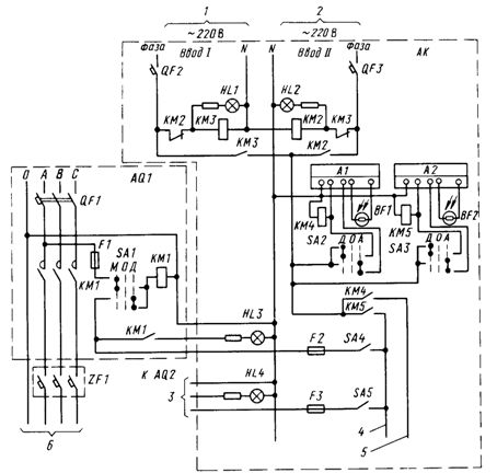
Rice. 5. Example of a light barrier control scheme.Option one: QF1 -QF3 — breaker; F1 -F3 — fuse; KM1 -KM5 — magnetic starter; A1 A2 — automatic photo switcher; BF1, BF2 — photoresistor; SA1 -SA3 — control selector (key); ZF1 — box with single-pole circuit breakers; HL1 -HL4 — armature of a light signal; SA4 -SA5 — switch; AQ1, AQ2 — power supply cabinet for light barriers from the first and second sources; AK — control cabinet; M — local authority; O — disabled; D — remote control; A — automatic control; 1,2 — inputs from the main and backup power supply of the control circuits; 3 — to the cabinet AQ2 of the second power supply, the circuit is similar to that of the cabinet AQ1 of the first power supply; 4 — to power cabinets for light barriers at other sites; 5 — to control circuits for outdoor lighting lines; 6 — to the lights of the light barriers.
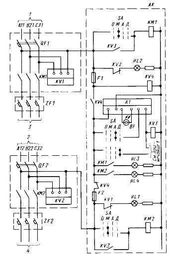
Rice. 6. Example of a light barrier control scheme. Option two: QF1, QF2 — breaker; KM1, KM2 — magnetic starter; KV1, KV2 — phase failure relay (together with lamps HL1 and HL2, they give a signal of failure at inputs 1 and 2); KV3, KV4 — intermediate relay; A1 — automatic photo switcher; BF — photoresistance; F1, F2 — fuse; SA — selector (key) control; HL1 -HL4 — light signaling fittings; AQ1, AQ2 — power supply cabinet for light barriers from the first and second sources; AK — control cabinet; O — disabled; M — local authority; A — automatic control; D — remote control; 1,2 — inputs from the first and second power sources of the light barriers; 3, 4 — to the lights of the light barrier.
Note. The scheme provides for the possibility of remote control from the enterprise's outdoor lighting control center.In this case, free block contacts of magnetic starters KM1, KM2 are used for signaling.
The scheme is designed for individual power supply and control of each obstacle (chimney), which is impractical in the conditions of large enterprises with a large number of high-rise buildings. Supply cabinets AQ1 and AQ2 are located in the workshop of which the chimney is a part. The AK control cabinet, depending on the overall outdoor lighting control scheme, is located either in the outdoor lighting control center or in the same location as the light barrier power supply cabinets AQ1 and AQ2.
Used materials from the book Obolentsev Yu. B. Electric lighting of general industrial premises.