Active dimensional control when processing machine tool parts
 Active control is the control that controls the machining process as a function of the dimensions of the part. With active dimensional control, you can signal the transition from roughing to finishing, retraction of the tool at the end of machining, tool change, etc. Control is usually automatic. With active control, machining accuracy increases and labor productivity increases.
Active control is often used to control grinding processes (Fig. 1) where high machining accuracy is required and the dimensional resistance of the abrasive tool is low. The probe mechanism 1 measures part D and gives the result to the measuring device 2. Then the measuring signal is transmitted to the converter 3, which converts it into electrical and through the amplifier 4 transmits it to the executive body of the machine 6. At the same time, the electrical signal is supplied to the signaling device 5. The supply of elements 2, 3, 4, the necessary forms of energy is carried out by block 7.Depending on the need, some elements can be excluded from this circuit (for example, element 5).
Electrical contact measuring transducers are widely used as primary transducers for active control (Fig. 2, a). With a decrease in the size of the workpiece, the rod 9 moves down into the bushings 7 pressed into the body 5. In this case, the limiter 8 presses the arm of the contact lever 2, fixed to the body using a flat spring 3. This causes a significant deviation to the right of the upper end of the contact lever 2, as a result of which the upper 4 first opens, and then the lower 1 contacts of the measuring head close.
Contacts can be adjusted. They are fixed in a strip 10 of insulating material. The body 5 is in the form of a clamp. It is covered with plexiglass covers on the sides, which allows you to observe the operation of the sensor. If it is necessary to observe the size of the workpiece in the hole 6, an indicator is strengthened, which is influenced by the upper end of the rod 9.
Electrocontact sensors with two contacts, which are activated one after the other during the processing of the workpiece, allow an automatic transition from rough grinding to finishing and then retracting the grinding wheel.
The active control primary transducer described refers to electrical contact dials. They combine an indicator and an electrical transducer. To prevent electroerosion destruction of the measuring contact passing through the base of the transistor (Fig. 2, b). In this circuit, before the IR contact closes, a positive potential is applied to the base of the transistor and the transistor closes.
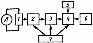
Rice. 1. Block diagram of active control
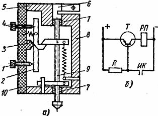
Rice. 2.Contact measuring transducer for control of dimensions and its inclusion
When the contact IK is closed, a negative potential is applied to the base of the transistor T, a control current arises, the transistor opens, and the intermediate relay RP operates, closing the executive and signal circuits with its contacts.
The industry produces semiconductor relays based on this principle and designed to send many commands, as well as electronic relays that are less durable.
On old machines from the 1960s and 1970s, pneumatic devices were widely used for active control. In such a device (Fig. 3), compressed air, pre-cleaned from mechanical impurities, moisture and oil through special moisture separators and filters, is supplied at a constant operating pressure through the inlet nozzle 1 to the measuring chamber 2. Through the measuring chamber nozzle 3 and the annular gap 4 between the front surface of the measuring nozzle and the surface of the workpiece 5 to be checked, air escapes.
The pressure established in chamber 2 decreases as the gap increases. The pressure in the chamber is measured with a pressure gauge for contact 6, and from its readings it is possible to estimate the size of the workpiece. At a certain pressure value, the measuring contacts close or open. Spring manometers are used to measure pressure.
Contact measuring devices are also used, in which a damper covering the air outlet is connected to the measuring tip.
Pneumatic tools usually operate at an air pressure of 0.5-2 N / cm2 and have a measuring nozzle diameter of 1-2 mm and a measuring gap of 0.04-0.3 mm.
Pneumatic tools provide high measurement accuracy. Measurement errors are typically 0.5-1 µm and can be further reduced in special measuring devices. The disadvantage of pneumatic devices is their significant inertia, which reduces control performance. Pneumatic devices consume significant amounts of compressed air.
Pneumatic tools essentially perform non-contact dimensional inspection. The distance between the measured part and the device is small, it depends on the working gap, which is usually tenths and hundredths of a millimeter. Method for non-contact control at a distance of 15-100 mm from the measured part.
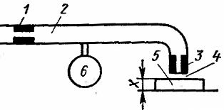
Rice. 3. Device for pneumatic active control
With this control (Fig. 4, a), the light from the lamp 1 is directed through the condenser 2, the slit membrane 3 and the lens 4 to the surface of the measured part 11, creating a glare in the form of a stroke on it. All these elements form the emitter I. The light detector II through the lens 5, the slit diaphragm 6 and the collecting lens 7 directs narrow stripes on the surface of the part 11, directing the reflected light flux into the photocell 8.
Emitter I and light receiver II are mechanically attached to each other so that the focusing points of objectives 4 and 5 are aligned. When the focal point is on the surface of the part to be inspected, the largest light flux enters the photocell F. Each time the tool moves up or down, the flux decreases, because the areas of illumination and observation diverge.
Therefore, when the device is lowered, the current Iph of the photocell, depending on the travel path, changes as shown in Fig. 4, b.
The current Iph passes through the differentiating device 9 (Fig. 4, a), which produces a signal at the moment of its greatest value. At this point, the readings of the primary transducer 10 are automatically recorded, indicating the displacement of the device relative to the initial position, thereby determining the desired size.
The accuracy of the measurement does not depend on the color of the tested surface, constant illumination from the side, partial contamination of the optics or aging of the emitting lamp. In this case, the maximum value of the photocurrent changes as shown in Fig. 4b with dashed line, but the position of the maximum will not change.
Photoresistors, photomultipliers, photocells with internal and external effect, photodiodes, etc. can be used as a photodetector.
The error of the described non-contact extreme photoconverter does not exceed 0.5-1 micron.
The scheme of automatic adjustment of a machine for continuous grinding of surfaces is shown in fig. 5.
Before leaving the rotating electromagnetic table, the machined parts 3 (for example rings with ball bearings) pass under the rotating flag 2. The grinding wheel 1 processes the part 3 in one pass; if the circle has not removed the required allowance, then part 3 touches the flag and it is reversed. In this case, the contact system 4 is activated, which gives a signal to lower the grinding disc from the drive 5 with a predetermined value.
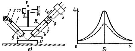
Fig. 4. Device for non-contact remote control of dimensions.
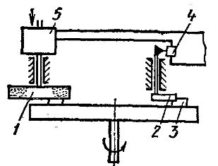
Rice. 5.Adjustment device for surface grinding machine
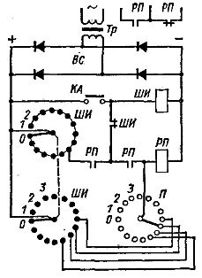
Rice. 6. Relay for counting pulses
In automatic machine control systems, a signal is sometimes required after a certain number of passes, divisions or machined parts. For these purposes, a pulse counting relay with a telephone pedometer is used. A step finder is a commutator, the brushes of several contact fields of which are moved from contact to contact with the help of an electromagnet and a ratchet mechanism.
A simplified diagram of the pulse counting relay is shown in Fig. 6. The P switch motor is set to a position corresponding to the number of pulses to be counted to send a command. Whenever the track switch contact KA opens, the brushes of the stepper SHI move one contact.
When the number of pulses set on the switch P is counted, the executive intermediate relay RP will turn on through the lower field contacts of SHI and P. At the same time, the self-power circuit of the relay RP and the self-recovery circuit of the stepper will be established in the initial its position, which is ensured by the supply of the search coil through its own open contact.
The seeker begins to work impulsively without an external command, and its brushes quickly move from contact to contact until they reach their initial position. In this position, in the upper field of SHI, the self-powering circuit of the relay RP is interrupted and the whole device comes to its initial position.
When it is necessary to increase the service life of the counters, as well as the counting speed, electronic counting schemes are used.Such devices are widely used in programmed control of metal cutting machines. In addition to the considered automation methods in mechanical engineering, control is sometimes used in the power function, e.g. etc. v. DC motor and other parameters. Such forms of management are used, in particular, in the automation of startup processes. Control is also used in a function of several parameters at the same time (for example, current and time).