Electrical equipment of planing machines
 Planer main motion drive: G-D system drive with EMU, two squirrel rotor asynchronous motors (for forward and reverse), electromagnetic clutch asynchronous motor, thyristor DC drive, frequency controlled asynchronous drive. Braking: dynamic, with recovery and reverse switching for DC motors and G-D system. Adjustment range up to 25:1.
Propulsion drive (periodic and transverse): mechanical from the main drive chain, asynchronous squirrel-cage motor, EMU-D system.
Auxiliary drives of planing machines are used for: rapid movement of the caliper, movement of the cross beam, clamping of the cross beam, lifting of the cutters, lubrication pump.
Special electromechanical devices and interlocks: electromagnets for raising the cutters, electro-pneumatic control for raising the cutters, lubrication control devices, interlocks to prevent the possibility of operation of the unclamped cross beam, with an inoperative lubrication pump.
The performance of planers is highly dependent on the return speed of the table.The time required for the working stroke of the table and its return to its original position,

where tn is the start time, tp is the running time (constant speed motion), tT is the deceleration time, t'n is the acceleration time during the reverse stroke, toxin is the steady state motion time during the reverse stroke of the table, t'T is the stopping time during the reverse course, ta is the response time of the equipment.
Increasing the velocity vOX of the return stroke of the mass leads to a decrease in the time t0X of the return stroke and therefore the duration of the time T of the double stroke. The number of double moves per unit time increases. The shorter the time tOX becomes, the less its change affects the time T of the double move and the number of double hits per unit time. Therefore, the effectiveness of increasing the reverse speed v0X gradually decreases as it increases.
Neglecting the time spent in transients and equipment operation, we have approx

The ratio of two double moves per unit time
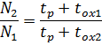
where toxi1 and toxi2 are the return stroke durations at the return speeds vox1 and vox2, respectively.
Let's take vox1 = vp (where vp is the cutting speed)

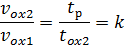

The last formula shows that as the backstroke speed increases, the increase in the number of double hits slows down. If we take into account the duration of transient processes, as well as the response time of the equipment, then the effectiveness of increasing the vox speed will be even less. Therefore k — 2 ÷ 3 is usually taken.
The duration of long-shot transients has little effect on performance.For short strokes, the number of strokes decreases significantly as the return time increases.
In order to reduce the reversing time, in some cases two half-power motors are used instead of one electric motor. In this case, the moment of inertia of the rotors turns out to be much smaller than that of an engine. The use of a worm gear in the table drive circuit results in a reduction in the total moment of inertia of the drive. However, there is a limit to reducing the reverse time. During the reversal period of the planers, a cross-periodic feeding of the calipers is performed, as well as raising and lowering of the cutters for the return stroke.
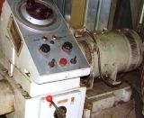
Grater
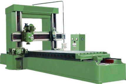
Cutting machines with different table drives operate in machine-building plants.
The movement of the table is done in many different ways. For a long time, two electromagnetic clutches were used to drive small planers. These clutches transmit rotation at different speeds corresponding to the forward and reverse speeds and engage sequentially. The couplings were connected to the motor shaft by means of belt or toothed gears.
Due to the significant electromagnetic and mechanical inertia, the reverse time of these drives is long and a lot of heat is generated in the couplings. Speed control is carried out by switching the gearbox, which works in difficult conditions and wears out quickly.
A generator-engine was used for heavy planers. It provides a wide range of smooth speed control. The G -D system with EMP is used to solve the range of speed adjustment of the drive of longitudinal planers.The disadvantages of such drives include large sizes and significant costs. A DC motor drive with parallel (independent) excitation is also used in some cases.
Table drive of planing machines of the Minsk Plant for Metal Cutting Machines named after V.I. The October Revolution (Fig. 1) was made according to the G-D system with EMB as the cause. The engine speed is controlled only by changing the generator voltage in the range 15: 1. The machine has a two-speed gearbox.
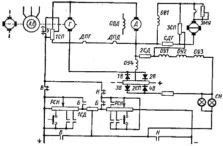
Rice. 1. Scheme of the table drive planer
A current determined by the difference between the reference voltage and the negative feedback voltage of the motor D flows through the coils OU1, OU2, OUZ of the control ECU. The reference voltage, when the engine D rotates forward, is removed by the PCV potentiometer , and when turning back from the PCN potentiometer. By moving the sliders on the PCV and PCN potentiometers, you can set different speeds. By automatically connecting to certain points of the potentiometers, it is possible to ensure the set rotation speeds in the corresponding sections of the cycle.
The feedback voltage is the difference between the part of the generator voltage G taken by the potentiometer 1SP and the voltage taken by the windings DPG and DPD of the additional poles of the generator and motor and is proportional to the motor current D.
Exciting coil OB1 of generator D is powered by EMU current. With resistors ZSP and SDG, the coil OB1 forms a balanced bridge. A 2SD resistor is included across the diagonal of the bridge. With each change in the current of the coil OB1, radiation occurs in it. etc. v. self-induction. The balance of the bridge is disturbed and a voltage appears across the 2SD resistor.The current in the coils OU1, OU2, OUZ simultaneously changes and while e. with, additional magnetization or demagnetization of the IMU is performed.
The OU4 EMU coil provides current limiting during transients. It is related to the difference between the voltage taken from the coils of DPG and DPD and the reference voltage of the potentiometer 2SP. Diodes 1B, 2B ensure current flow in coil OU4 only at high motor currents D when the first of these voltages is greater than the second.
The difference between the reference voltage and the feedback voltage during the entire transient must remain large enough. The compensation of non-linear dependencies is carried out using non-linear elements: diodes 3V, 4V and SI lamps with a non-linear resistance filament. The range of rotation frequency adjustment in desktop drives according to the G-D system extends the change in the magnetic flux of the motor. Thyristor drives are also used.
Glass slides are usually fed back for a short time. The feeding process must be completed at the beginning of a new work stroke (to avoid breaking the cutters). Powering is done mechanically, electrically and electromechanically, with separate motors for each slide or one common motor for all slides. The movement to position the caliper is usually performed by the feed motor with a corresponding change in the kinematic scheme.
In order to change the value of the periodic transverse feed, in addition to the well-known ratchet devices, electromechanical devices based on different principles are used.In particular, a time relay is used to regulate the intermittent power supply, the setting of which can be changed over a wide range.
The time relay turns on at the end of the work stroke at the same time as the cross feed motor. Turns this motor off after a time corresponding to the relay setting. The size of the transverse feed is determined by the duration of rotation of the electric motor. The constancy of the power supply requires the constancy of the motor speed and the duration of its transients. An EMC drive is used to stabilize the speed. The duration of the starting and stopping processes of the electric motor is reduced by forcing these processes.
To change the lateral feed, a regulator acting as a function of the trajectory (Fig. 2) is also used, this is a directional device that turns off the motor after the caliper has traveled a certain path. The regulator has a disk on which cams are fixed at equal distances. When the engine is running, the disc, which is kinematically connected to its shaft, rotates while the next cam acts on the contact. This leads to disconnection of the electric motor from the network.
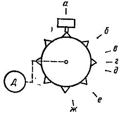
Fig. 2. Regulator of the transverse feed of the planer
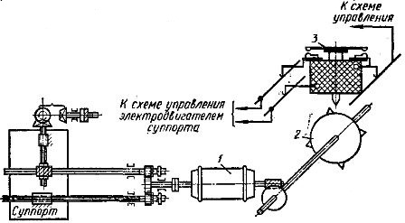
Rice. 3. Feed system of planer 724
However, the motor continues to run for a while. In this case, an angular path greater than that set on the regulator will be traversed. Thus, the emission value will correspond not to path ab, but to path ab. At the next periodic feed, the distance corresponding to the arc bg may be too small to accelerate the motor to the set speed.Therefore, when the motor is turned off with the cam r, the speed of rotation of the motor will be less and therefore the path rd traveled by inertia will be less than in the previous intermittent feed. Thus we obtain the second feed corresponding to the arc v less than the first.
To accelerate the motor on the next cross-feed, a larger de-trajectory is again provided. The speed of the engine at the end of its acceleration will be higher and therefore the amount of coasting will also increase. Thus, with a small amount of cross-feeding, large and small feeds will alternate.
An unregulated squirrel-cage induction motor can be used for a cross-feed regulator of the type under consideration. The amount of cross feed can be adjusted by changing the gear ratio of the kinematic chain connecting the motor shaft to the drive disc. The number of cameras on the disk can be changed.
By using electromagnetic multilayer connectors, the transient time is significantly reduced. These clutches provide fairly fast action (10-20 or more starts per second).
The machine feed system 724 is shown in FIG. 3. The amount of feed is set by the disc 2 with spikes, which begins to rotate when the electric motor 1 is turned on. Above this disc, an electromagnetic relay 3 of the caliper power supply is placed, which is turned on simultaneously with the power motor. When relay 3 is on, the rod is lowered so that the spikes on the rotating disc can touch it.
In this case, the relay contacts are closed.When the disc spike lifts the stem, the relay contacts open and the motor is disconnected from the mains. To ensure the required number of feeds, a set of discs with different numbers of spikes is used. The disks are mounted next to each other on a common axis. The power relay can be moved so that it can work with any drive.
Electromagnets are often used to lift cutters during the return stroke. Usually, each cutting head is served by a separate electromagnet (Fig. 4, a). Heads descend under the influence of gravity. An air valve is used to soften the blow from heavy heads.
Smoother lifting and lowering of the cutting head can be achieved by using a reversible electric motor rotating the eccentric (Fig. 4, b). This cutter lift is used on heavy machinery. Moving and clamping the cross beam of the planers is done in the same way as for rotary lathes.
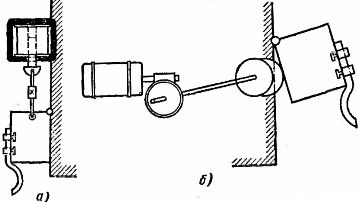
Rice. 4. Lifting cutters when planing
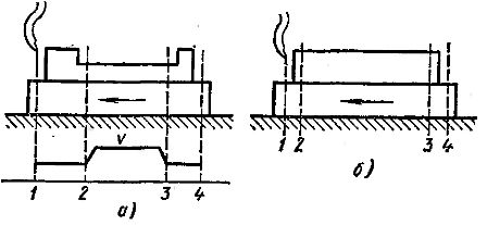
Rice. 5. Automatic change of feed rate of the planer table
Turning machines often have to machine parts that have holes or recesses that cannot be machined. In this case, it is recommended to change the speed of movement of the table (Fig. 5, a). The mass will travel through the hole at an increased velocity equal to the return velocity.
When machining a workpiece with longitudinal planing machines that does not have holes and recesses (Fig. 5, b), it is possible to reduce the time of the machine by increasing the cutting speed in section 2-3.In sections 1-2 and 3-4, the speed is reduced to avoid breaking the tool and crushing the front edge of the workpiece during driving, as well as cutting the material when the tool exits.
In both described cases variable devices are used. The change in speed is effected by direction switches which are influenced by the cams placed at the corresponding points on the road.
In the case of cross-planers and grinders, the stroke of the slide is small, and the reciprocating motion is effected by a rocking gear. The increase in the speed of the slider during the return stroke is provided by the same roller. The electrification of the cross-planer is simple and boils down to the use of irreversible squirrel-cage motors and the simplest contactor control circuits.