Regulation of asynchronous motors
 Adjustment of asynchronous motors is carried out in the following range:
• visual inspection;
• checking the mechanical part;
• measurement of the insulation resistance of the coils relative to the body and between the coils;
• measuring the resistances of the windings to direct current;
• testing of coils with increased voltage at industrial frequency;
• trial run.
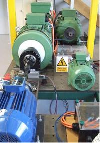
External inspection of the induction motor start from the control panel.
The plate must contain the following information:
• name or trademark of the manufacturer,
• type and serial number,
• nominal data (power, voltage, current, speed, coil connection diagram, efficiency, power factor),
• year of issue,
• weight and GOST for the engine.
Getting to know the engine shield at the beginning of the work is required. Then they check the condition of the outer surface of the engine, its bearing assemblies, the output end of the shaft, the fan and the condition of the terminal terminals.
If a three-phase motor does not have composite and sectioned stator windings, then the terminals are designated in accordance with the table.1, and in the presence of such coils, the terminals are designated with the same letters as ordinary coils, but with additional numbers in front of capital letters. For multi-speed asynchronous motors before the letters are numbers indicating the number of poles in that section.
table 1
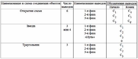
table 2
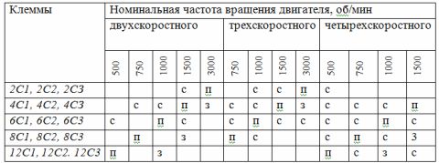
Note: terminals numbered P — connected to the network, C — free, Z — short circuit
The marking of the shields of multi-speed motors and the methods of switching them on at different speeds can be explained with the help of Table. 2.
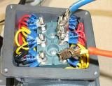
When inspecting an induction motor, special attention should be paid to the condition of the terminal box and output ends, where various insulation defects are very common, while measuring the distance between the live parts and the housing. It should be large enough so that the surface does not overlap. Equally important is the value of the shaft runout in the axial direction, which, according to the standards, should not exceed 2 mm (1 mm in one direction) for motors with a power of up to 40 kW.
The size of the air gap is of great importance, as it has a significant impact on the characteristics of asynchronous motors, therefore, after repair or in case of unsatisfactory operation of the motor, the air gap is measured at four diametrically opposite points. The clearances must be uniform over the entire circumference and must not differ at any of these four points by more than 10% of the average value.
Asynchronous motors in various machine tools, such as thread and gear grinders, have special leakage and vibration requirements.The shaft runout and vibration of electrical machines are greatly affected by the machining accuracy and condition of the machine's rotating parts. Shocks and vibrations are particularly high when the motor shaft is bent.
Runout — deviation from a given (correct) relative position of the surfaces of rotating or oscillating parts such as bodies of rotation. Distinguish between radial and end strokes.
For all machines, leakage is undesirable, as it disrupts the normal operation of the bearing assemblies and the machine as a whole. Leakage is measured with a dial that can measure strokes from 0.01mm to 10mm. When measuring shaft runout, the tip of the indicator rests on the shaft, which rotates at low speed. The deviation of the hour indicator hand estimates the value of the runout, which must not exceed the values specified in the technical specifications for the machine or engine.
Insulation of electrical machines is an important indicator, because the durability and reliability of the machine depends on its condition. According to GOST, the insulation resistance of windings in MΩ of electrical machines should be at least
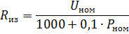
where Un — nominal winding voltage, V; Pn — nominal power of the machine, kW.
Insulation resistance is measured before the test start of the engine, and then periodically during operation; in addition, they are observed after long interruptions in operation and after any emergency shutdown of the drive.
If the start and end of each phase are traced in the motor, then the insulation resistance is measured separately for each phase relative to the case and between the windings. In multi-speed motors, the insulation resistance is checked for each winding separately.
Voltages up to 1000 V are used to measure the insulation resistance of electric motors megameters for 500 and 1000 V.
The measurement is carried out as follows, the clamp for the megohmmeter «Screen» is connected to the body of the machine, and the second clamp is connected to the terminal of the coil with a flexible wire with reliable insulation. The ends of the wires must be sealed with handles of insulating material with a pointed metal pin to ensure a reliable contact.
The megger handle rotates at a frequency of approximately 2 rps. Small motors have a small capacity, so the needle of the device is set to a position corresponding to the insulation resistance of the machine winding.
For new machines, the insulation resistance, as practice shows, fluctuates at a temperature of 20 ° C in the range of 5 to 100 megohms. To motors with low-critical drives with low power and voltage up to 1000 V «Rules for electrical installations» do not impose specific requirements on the value of R.From practice, there are cases when motors with resistances of less than 0.5 megohm are put into operation, their insulation resistance increases, and later they work without problems.
The decrease in insulation resistance during operation is caused by surface moisture, contamination of the insulation surface with conductive dust, moisture penetration into the insulation, and chemical decomposition of the insulation. To clarify the reasons for the decrease in insulation resistance, it is necessary to measure it using a double bridge, for example R-316, with two current directions in the controlled circuit. With different measurement results, the most likely cause is the penetration of moisture into the thickness of the insulation.
In particular, the question of commissioning an induction motor should be decided only after testing the windings with increased voltage. The inclusion of a motor with a low value of insulation resistance without an overvoltage test is allowed only in exceptional cases, when the question is decided which is more profitable: to endanger the motor or to allow downtime of expensive equipment.
During the operation of the motor, damage to the insulation, leading to a decrease in its dielectric strength below the permissible standards... According to GOST, the test of the dielectric strength of the insulation of the windings with respect to the case and between them is carried out with the motor disconnected from the network for 1 minute with test voltage, the value of which must be not less than the value given in the table. 3.
Table 3
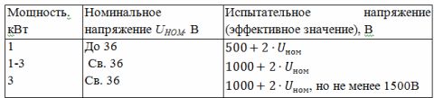
The increased voltage is applied to one of the phases, and the remaining phases are connected to the motor casing. If the windings are connected inside the motor in star or delta, the insulation test between the winding and the frame is carried out simultaneously for the entire winding. Voltage cannot be applied instantaneously during testing. The test starts with 1/3 of the test voltage, then the voltage is gradually increased to the test voltage, and the rise time from half to the full test voltage shall be at least 10 s.
Full voltage is maintained for 1 minute, then gradually reduced to 1 / 3Utest and the test setting is turned off. The test results are considered satisfactory if during the test there was no breakdown of the insulation or overlap on the surface of the insulation, while no sharp shocks were observed on the instruments, indicating partial damage to the insulation.
If a fault occurs during the test, a place is found with it and the coil is repaired. The location of the fault can be determined by re-applying voltage and then watching for sparks, smoke, or a slight pop when no sparks are visible externally.
DC measurement of the resistance of the windings, which is carried out to clarify the technical data of the circuit elements, makes it possible in some cases to determine the presence of a short circuit. The temperature of the windings during measurement should not differ from the ambient by more than 5 ° C.
Measurements are made using a single or double bridge, by the ammeter-voltmeter method or by the microohmmeter method.Resistance values should not differ from the average by more than 20%.
According to GOST, when measuring the resistance of the windings, each resistance must be measured 3 times. When measuring coil resistance by the ammeter-voltmeter method, each resistance must be measured at three different current values. The arithmetic mean value of three measurements is taken as the actual resistance value.
The ammeter-voltmeter method (Fig. 1) is used in cases where high measurement accuracy is not required. Measurement by the ammeter-voltmeter method is based on Ohm's law:
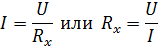
where Rx — measured resistance, Ohm; U- voltmeter reading, V; I ammeter reading, A.
The accuracy of measurement with this method is determined by the total error of the instruments. So if the accuracy class of the ammeter is 0.5% and that of the voltmeter is 1%, then the total error will be 1.5%.
In order for the ammeter-voltmeter method to give more accurate results, the following conditions must be met:
1. the accuracy of measurement largely depends on the reliability of the contacts, therefore it is recommended to solder the contacts before measurement;
2. the source of direct current must be a network or a well-charged battery with a voltage of 4-6 V to avoid the influence of voltage drop at the source;
3. the reading of the instruments must be done simultaneously.
Resistance measurement using bridges is mainly used in cases where it is necessary to obtain greater measurement accuracy. Accuracy bridging methods reaches 0.001%. Bridge measurement limits range from 10-5 to 106 ohms.
A microohmmeter measures a large number of measurements, for example, contact resistances, connections between coils.
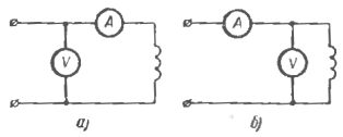
Rice. 1. Scheme for measuring the resistance of DC coils by the ammeter-voltmeter method
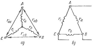
Rice. 2. Scheme for measuring the resistance of the stator winding of an induction motor connected in star (a) and delta (b)
Measurements are made quickly as there is no need to adjust the instrument. The resistance of the DC winding for motors with a power of up to 10 kW is measured not earlier than 5 hours after the end of its operation, and for motors over 10 kW — not less than 8 hours with a stationary rotor. If all six ends of the windings are removed from the motor stator, then the measurement is made on the winding of each phase separately.
When the windings are internally connected to a star, the resistance of two phases connected in series is measured in pairs (Fig. 2, a). In this case, the resistance of each phase
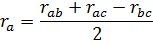
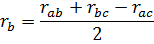
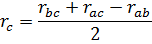
With an internal delta connection, measure the resistance between each pair of output ends of the linear clamps (Fig. 2, b). Assuming that the resistances of all phases are equal, the resistance of each phase is determined by:
For multi-speed motors, similar measurements are made for each winding or for each section.
Checking the correct connection of windings of AC machines. Sometimes, especially after repair, the water ends of the induction motor turn out to be unmarked, it becomes necessary to determine the beginning and ends of the windings. There are two most common ways to determine.
According to the first method, the ends of the windings of the individual phases are first determined in pairs. The circuit is then assembled according to fig. 3, a.The "plus" source is connected to the beginning of one of the phases, "minus" to the end.
C1, C2, C3 are usually taken as the beginning of phases 1, 2, 3 and C4, C5, C6 — at the ends 4, 5, 6. At the moment of switching on the current in the windings of other phases (2-3) is induced electromotive force with polarity "minus" at the beginning of C2 and C3 and "plus" at the ends of C5 and C6. At the moment when the current is off in phase 1, the polarity at the ends of phases 2 and 3 is opposite to the polarity when they are on.
After marking phase 1, the source of direct current is connected to phase 3, if at the same time the needle of the millivoltmeter or galvanometer deviates in the same direction, then all the ends of the windings are marked correctly.
To determine the start and end according to the second method, the motor windings are connected to a star or delta (Fig. 3, b), and a single-phase reduced voltage is applied to phase 2. In this case, between the ends of C1 and C2, as well as C2 and C3, a voltage arises that is slightly greater than the supplied one, and between the ends of C1 and C3 the voltage turns out to be zero. If the ends of phases 1 and 3 are connected incorrectly, the voltage between the ends of C1 and C2, C2 and C3 will be less than supplied. After the mutual determination of the marking of the first two phases, the third is determined in a similar way.
Initial activation of the induction motor. To establish the full serviceability of the engine, it is tested at idle and under load. Recheck the condition of the mechanical parts by filling the bearings with grease.
The ease of movement of the motor is checked by turning the shaft by hand, while there should be no crackling, rattling and similar sounds indicating contact between the rotor and the stator, as well as the fan and the housing, then the correct direction of rotation is checked, for this the engine turns on briefly.
The duration of the first activation is 1-2 s. At the same time, the starting current value is monitored. It is recommended to repeat the short-term start of the engine 2-3 times, gradually increasing the duration of switching on, after which the engine can be switched on for a longer period. While the engine is idling, the regulator must make sure that the running gear is in good condition: no vibrations, no current surges, no heating of the bearings.
If the results of the test runs are satisfactory, the engine is switched on together with the mechanical part or tested on a special stand. The time for checking the operation of the engine varies from 5 to 8 hours, while monitoring the temperature of the main blocks and windings of the machine, the power factor, the state of lubrication of the bearings of the units.