Designs of heating elements for electric furnaces
 The heating elements of most industrial furnaces are either strip or wire. In fig. 1 shows the device of a conventional nichrome wire heater, the constructions adopted for fixing it on the roof, on the walls and in the hearth of the furnace, and the design of the wires. Typically, for the production of heaters for industrial furnaces, wire with a diameter of 3 to 7 mm is used. However, for furnaces with an operating temperature of 1000 ° C and more, a wire with a diameter of less than 5 mm should not be taken.
The ratios between the pitch h of the spiral and its diameter D and the diameter of the wire d (Fig. 1, k) are chosen in such a way as to facilitate the placement of the heaters in the furnace, to ensure their sufficient rigidity and at the same time not heat transfer from them to the products is excessively complicated.
The larger the diameter of the spiral and the thicker its pitch, the easier it is to place heaters in the furnace, but as the diameter increases, the strength of the spiral decreases and the tendency of its turns to lie on top of each other increases .On the other hand, as the density of the winding increases, the shielding effect of the part of its turns facing the products on the rest increases and, therefore, the use of its surface deteriorates.
Practice has established quite definite, recommended ratios between wire diameter, pitch and spiral diameter for wires from 3 to 7 mm in diameter. These ratios are as follows: h> 2d and D = (6 ÷ 8) d for nichrome and for less strong iron-chromium-aluminum alloys D = (4 ÷ 6) d.
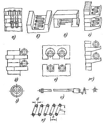
Rice. 1. Wire heaters: a — zigzag wire heater on metal hooks on the side wall: b — zigzag wire heater in the hearth, c — the same in the vault, d — the same on ceramic shelves, e — wire spiral on protruding bricks on the side wall c by connecting to hooks, f — wire helix in arched stones and in hearth shafts, g — wire helix on ceramic shelves, h — wire helix on ceramic pipe, and — wire heater outlet, k — symbolic designation of the dimensions of the heater with wire
For thinner wires, the ratio of the diameters of the helix and the wire, as well as the pitch of the helix, are usually taken larger. These ratios apply to spirals placed on shelves (so that the spirals do not swell, they must be tied every 300 — 500 mm to hooks embedded in the masonry) and in the channels of the lining of walls and vaults, as well as in vaulted stones.
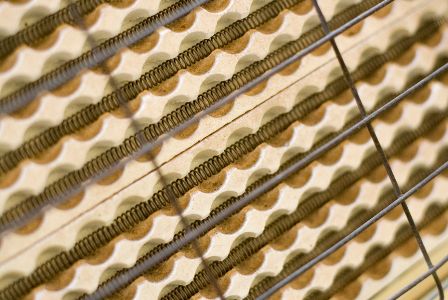
Recently, however, spiral heaters based on ceramic tubes have become more common (Fig. 2).From the point of view of distribution of radiation and power on the walls of the furnace, such heaters are almost equivalent to free-radiating spirals, and conversely, they are much more efficient than spirals in channels or on shelves.
On the other hand, with them, each bend rests on the surface of the tube, and even if it sags to some extent (acquires ovality) when heated, this does not reduce its characteristics. Since such a heater, therefore, is less loaded than others, and in it individual turns cannot lie on top of each other, then, if necessary, it can bring the ratio of the diameter of the spiral to the diameter of the wire up to 10 , and for iron-chromium-aluminum alloys - up to 8.
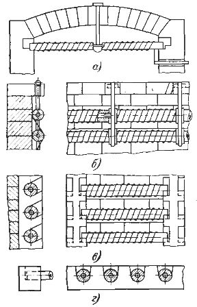
Rice. 2. Designs of spiral heaters with wire on ceramic pipes: a — arc heaters, b — pipes on the side walls, fixing on heat-resistant suspensions, c — the same in the grooves of ceramic pillars, d — pipes in the hearth.
This design is particularly favorable for the latter as it allows the material to expand freely. In addition, as Fig. 2, designs of heaters with wire on ceramic tubes have been developed for their installation not only on the walls of the furnace, but also in the roof and in the hearth, and in the latter cases the heaters can be made in the form of movable frames, such frames can be easily inserted into the furnace and replaced during firing. spare without stopping the furnace.
Thus, the design of spiral heaters with wire on ceramic tubes is versatile both in terms of the use of materials and the location of the heaters in the furnace chamber.The ratio of the inner diameter of the spiral to the outer diameter of the tube for such heaters can be taken as approximately 1.1-1.2, the distance between the axes of the tubes 1.5-2 times the diameter of the spiral.
For electric heaters and furnaces with forced air circulation, the use of spiral heaters on ceramic tubes is less desirable, since this reduces the heat transfer coefficient of the heater, the use of spirals on the shelves or in the lining channels is completely unacceptable for the same reason ( except for cases where the gas flow can be directed along the spiral, in the direction of its axis).
In such furnaces, it is better to use structures with freely blown spirals, clamped between insulators at certain intervals or tied to the latter (Fig. 3). If spiral heaters of ceramic tubes are used in such structures (at higher temperatures), then the ratio of the diameter of the spiral to the diameter of the tube should be increased to 1.5.
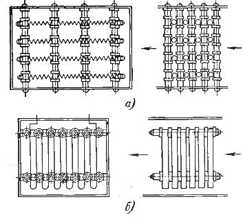
Rice. 3. Designs of (a) wire and (b) strip heating elements of electric heaters.
Tape heaters are made in the form of zigzags of various sizes and are mounted on metal (heat-resistant steel or nichrome) or ceramic hooks (Fig. 4). Metal hooks are embedded in the masonry of the walls (in the seams between bricks or in the channels of special bricks), ceramic hooks are outgrowths of special stones laid in the masonry.
For the lower parts, the zigzags do not close when warping, spacers are placed between them, which are fireclay or aluminum ceramic bushings placed on heat-resistant or nichrome pins embedded in the masonry.The bushings are attached to the pins with nichrome pins. With ceramic hooks, the separators are also made entirely of ceramics (Fig. 4, a).
In fig. 4, h shows the design of removable ceramic hooks and spacers. This design is very useful as it allows you to easily replace the hooks in case of damage.
Zigzag heaters can also be mounted on the side walls of the furnace on ceramic racks, but this design is even less convenient in terms of specific power placed on the wall and the degree of shielding of the heaters than the construction of wire-on-rack heaters . To this, it should be added that ceramic shelves usually perform poorly in operation, since in case of their breakage, in order to replace the damaged shelf, it is necessary to shift the masonry (Fig. 4, d).
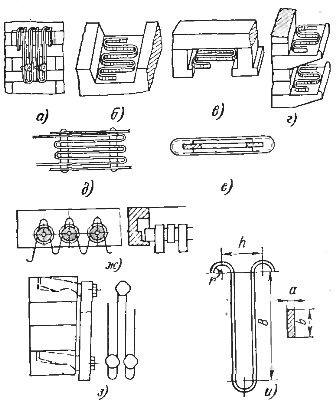
Rice. 4. Designs of strip heaters: a — strip zigzag heaters on the side wall of metal hooks, b — strip zigzag heater in the hearth. c — same in vault, d — same on ceramic shelves, e — movable high temperature frame element, f — low temperature frame element, g — flat wave heater on ceramic tubes, h — zigzag band heater on movable hooks and — symbolic designation on the dimensions of the band zigzag heater.
In the vault or at the bottom of the strip heaters, they can fit into the channels of the masonry, formed by special shaped stones (beams — Fig. 4, b and c). Such heaters can also be made as movable frames (Fig. 4-53, e). In addition, with an arched vault, the zigzags of the tape can be hung on movable metal hooks.
In electric heaters and forced-air furnaces, band heaters should be designed so that the surface of the heater is as accessible as possible for blowing with a gas stream. An example of such a construction is shown in fig. 3, b.
The thicker the zigzag heaters, the longer the heater can be placed in the oven, but the greater the protection of the turns, the worse the surface of the belt. Therefore, the accepted dimensions of strip zigzag heaters were established, which ensure their sufficient strength and low mutual protection.
For this purpose, they try to satisfy the following ratios (notations according to Fig. 4, i): b / a = 5 ÷ 20, the most common ratio of the width of the strip to its thickness is 10. zigzag step h> 1.8b , the strip radius is rounded to avoid bending fracture r>
For heater temperatures up to 1000 ° C in industrial furnaces, a tape with dimensions of at least 1X10 mm is used, at higher temperatures, at least 2X20 mm.
At temperatures up to 1000 ° C, the height of zigzag B on the wall can vary from 150 to 400-600 mm, but for every 200 mm a row of spacers is needed, that is, at 200-400 mm, one row of spacers, and at 400 —600 mm - two lines. On the arch and in the hearth, in order to avoid the heaters settling, the height of the zigzag B must be limited to 250 mm. These recommendations can be extended to iron-chromium-aluminum alloys.
For heater temperatures from 1000 to 1100 ° C, the specified limit dimensions can be reserved for the Kh20N80 and Kh20N80T alloy, for the iron-chromium-aluminum alloys, dimension B with the vertical position of the zigzag should be limited to 250 mm, and with horizontal position 150 mm.
At heater temperatures above 1100 ° C, the only acceptable design of strip heaters for both the roof and the bottom is a flat wave on ceramic tubes (Fig. 2, g). The length of the zigzag B in this case can be taken as 75-100 mm. For sidewall heaters, a design with ceramic hooks can be used, limiting the zigzag height to 150mm.
In recent years, zigzag wire heaters have been widely used. For these heaters, the zigzag step h is taken equal to (5 ÷ 9) d.
When using iron-chromium-aluminum alloys in furnaces with an operating temperature above 1000 ° C, all parts of refractory masonry that can come into contact with the heaters (ceramic hooks and dividers, shelves, pipes, channels, etc.) must be made of high-oxide aluminum materials with a minimum content of iron oxides.
Tape zigzags are usually wound by hand using a simple lever device. Spirals are wound on a lathe on a smooth mandrel tightly, then the resulting spiral is stretched to the desired pitch.
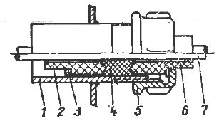
Rice. 5. Sealed heater outlet: 1 — housing, 2, 6 — insulating sleeves, 3 — spacer ring, 4 — asbestos gasket, 5 — coupling nut, 7 — heater outlet.
Since after removing the spiral from the mandrel, it unrolls a little, increasing its diameter (by about 1-3 mm), the mandrel should be taken with a smaller diameter than calculations.This reduction depends on the elasticity of the material and must be determined experimentally for each batch. In power plants, zigzag heaters are produced on special machines.
Outlets of heaters up to a temperature of 1000 ° C are made of heat-resistant steel, chrome-nickel or chrome, for higher temperatures - of alloy 0X23Yu5A (EI-595). For this purpose, take a wire rod, a rod with a cross-section equal to 3-4 times the cross-section of the heater, to reduce the release of heat in the wires. The part of the outlet located in the low temperature zone, in order to save expensive materials, can be made of ordinary carbon steel. Typical lead designs for wire and strip heaters are shown in Fig. 5.
In zigzag strip heating elements, the mutual shielding of the individual zigzags is still relatively large, even with a pitch exceeding twice the width of the strip. It would be more advantageous to design the heaters in such a way that the strip faces the product with on the broad side, but this requires a lot of welding as each turn of the strip has two welds and the heater design is expensive and prone to warping.
Therefore, although such heaters are used in some cases, but only for small furnaces. They provide significant material savings compared to strip and especially wire heaters and allow you to get a slightly higher specific wall surface power for the same material consumption.
Heaters with cast rims, cast from nichrome and hung on special hooks, also approach flat heaters (Fig. 6).The various heaters, of course, can only be made with large cross-sections, and therefore they are either used in large furnaces or require reduced voltage. Their advantage is high reliability and a long service life, measured in tens of thousands of hours. It is generally believed that properly calculated and designed nichrome heaters should operate from 6000 to 12000 hours (under current).
In muffle and tube furnaces, wire and strip heaters are wound directly on a ceramic muffle or tube, moreover, so that the turns of the coil during the expansion from heating do not weaken and do not move from their place, ceramics are supplied with channels in which the tape or wire is laid. Another way to fix the turns of the heater on the ceramic is to coat the latter after winding with a layer of refractory clay with fireclay.
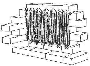
Rice. 6. Summer heaters.
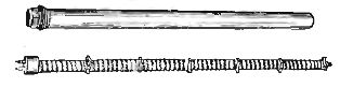
Rice. 7. Rod tube heaters.
In furnaces up to temperatures of 400-500 ° C, there are many more types of heaters. In addition to spiral and band zigzag heaters with an open wire, the same as in higher temperature furnaces, there are interchangeable heating element designs, convenient in that they can be used to produce any power and at the same time when they burn out, such elements are easily replaced. spare.
Tubular rod heating elements are a set of porcelain insulators strung on a heat-resistant or steel rod and placed in a steel tube, welded at one end and closed with a lead insulator at the other. A nichrome spiral is wound on porcelain insulators welded at one end to the insulator wire and at the other to the center rod.
Sometimes the space between the pipe and the heater is filled with quartz sand. Heaters of this type can be used up to 400-500 ° C and with refractory tubes up to 1000 ° C and are especially convenient for large furnaces in which it is necessary to protect the heater from mechanical damage or from the action of corrosive vapors (Fig. 7).
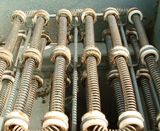
Of great interest are the so-called "tubular" heating elements (Fig. 8). They consist of a steel tube, along the axis of which a nichrome spiral is located, welded to the output bolts at the ends of the heater. The space between the spiral and the walls of the tube is filled with periclase, crystalline magnesium oxide, which has good electrical insulation and at the same time high thermal conductivity. The production of heating elements is carried out as follows.
A nichrome spiral wound on a steel rod was mounted strictly axially in the prepared cleaned steel tube, the tube was fixed vertically on a vibrating machine and filled with periclase powder passed through the magnetic separator. The rod is then removed from the pipe and passed through a forging machine, which hammers it around the circumference, causing its diameter to decrease and the periclase to become very compacted.
Sealed lead insulators are attached to the edges of the tube, after which, thanks to the periclase gasket, it can be bent in any way and given a convenient shape. In this form, the tubular elements can be used to heat air (electric heaters), oil, nitrates and even to melt low-melting metals such as tin, lead, babbitt.In the latter case, in order to avoid rapid corrosion of the metal pipe wall, it is pre-filled with cast iron, which forms a massive plate, inside which there is a tubular heating element.
Rice. 8. Tubular heaters.
The use of tubular heaters for baths with saltpeter is highly desirable, because compared to baths with external heating, it reduces the reduction of energy consumption, increases the safety of the baths and a huge saving of nichrome. However, for their satisfactory operation in nitrates, especially at temperatures of 500 ° C and above, it is necessary to make a double jacket of the tube, placing on the prepared heater a second tube, nickel, resistant to heat.
When used in electric heaters, they are finned to increase heat transfer to the air.
Tubular heaters are very widespread for the production of household heating devices.
Tubular heaters operate with power from several hundred watts to several kilowatts.
Data on tube heaters manufactured by our industry are available in the catalogs.