Dielectric heating
What is dielectric heating
 Dielectric heating refers to the heating of dielectrics and semiconductors in an alternating electric field under the influence of which the heated material is polarized. Polarization is a process of displacement of associated charges, leading to the appearance of an electric moment at each macroscopic volume element.
Polarization is divided into elastic and relaxation: elastic (without inertia) determines the energy of the electric field, and relaxation (inertial) determines the heat released in the heated material. In relaxation polarization by an external electric field, work is done to overcome the forces of the internal bonds ("friction") of atoms, molecules, charged complexes. Half of this work is converted into heat.
The power released in a dielectric is usually referred to a unit of volume and is calculated by the formula

where γ is the complex conjugate conductance of the material, EM is the electric field strength in the material.
Complex conduction

Here, εr is the total complex dielectric constant.

The real part of ε', called the dielectric constant, affects the amount of energy that can be stored in a material. The imaginary part of ε «, called the loss factor, is a measure of the energy (heat) dissipated in the material.
The loss factor takes into account the energy dissipated in the material due to both polarization and leakage currents.
In practice, calculations use a value called the loss angle tangent:

The tangent of the loss angle determines the ratio of the energy spent on heating to the stored energy of electromagnetic oscillations.
Considering the above, the volumetric specific active power, W / m3:

or

Thus, the specific volume power is proportional to the square of the electric field strength in the heated material, the frequency and the loss factor.
The strength of the electric field in the heated material depends on the applied voltage, the dielectric constant ε ', the location and shape of the electrodes that form the field. For some of the most common cases in practice, the location of the electrodes, the strength of the electric field is calculated by the formulas shown in Figure 1.
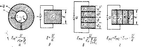
Rice. 1. To the calculation of the strength of the electric field: a — cylindrical capacitor, b — flat single-layer capacitor, c, d — flat multilayer capacitor with an arrangement of layers of materials, respectively, in transverse and along the electric field.
It should be noted that the limiting maximum value of Em is limited by the electrical strength of the heated material. The voltage should not exceed half of the breakdown voltage.The capacity for seeds of grain and vegetable crops is taken in the range (5 … 10) 103 V / m, for wood — (5 … 40) 103 V / m, polyvinyl chloride — (1 … 10 ) 105 V / m.
The loss coefficient ε « depends on the chemical composition and structure of the material, its temperature and moisture content, on the frequency and strength of the electric field in the material.
Dielectric heating characteristics of materials
Dielectric heating is used in various industries and agriculture.
The main characteristics of dielectric heating are as follows.
1. Heat is released in the heated material itself, which makes it possible to accelerate heating by tens and hundreds of times (compared to convective heating). This is especially noticeable for materials with low thermal conductivity (wood, grain, plastics, etc.).
2. Dielectric heating is selective: the specific volumetric power and, accordingly, the temperature of each component of an inhomogeneous material is different. This function is used in agriculture, for example in disinfecting grain and pickling silkworms,
3. During dielectric drying, heat is released inside the material and therefore the temperature in the center is higher than in the periphery. Moisture inside the material moves from wet to dry and from hot to cold. So, during convective drying, the temperature inside the material is lower than at the periphery, and the flow of moisture due to the temperature gradient prevents moisture from moving to the surface. This greatly reduces the effectiveness of convective drying. In dielectric drying, the moisture fluxes due to the temperature difference and the moisture content coincide.This is the main advantage of dielectric drying.
4. When heating and drying in an electric field with a high frequency, the loss coefficient decreases and, accordingly, the power of the heat flow. To keep the power at the required level, you need to change the frequency or voltage supplied to the capacitor.
Dielectric heating installations
The industry produces both specialized high-frequency installations intended for heat treatment of one or several types of products, as well as installations for general use. Despite these differences, all high-frequency installations have the same structural diagram (Fig. 2).
The material is heated in the working capacitor of the high-frequency device 1. The high-frequency voltage is supplied to the working capacitor through the block of intermediate oscillating circuits 2, designed for power regulation and generator regulation 3. The lamp generator converts the direct voltage received from the semiconductor rectifier 4, in high frequency alternating voltage. At the same time, at least 20 ... 40% of all the energy received from the rectifier is spent in the lamp generator.
Most of the energy is lost at the anode of the lamp, which must be cooled by water. The anode of the lamp is supplied with respect to the earth 5 … 15 kV, therefore the system of isolated supply of cooling water is very complex. Transformer 5 is designed to increase the network voltage to 6 ... 10 kV and disconnect the conductive connection between the generator and the electrical network. Block 6 is used to turn on and off the installation, sequentially perform technological operations and protect against emergency modes.
Dielectric heating installations differ from each other in the power and frequency of the generator, in the construction of auxiliary equipment designed for moving and holding the processed material, as well as for mechanical impact on it.
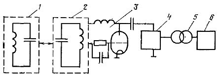
Rice. 2. Block diagram of the high-frequency installation: 1 — high-frequency device with a load capacitor, 2 — a block of intermediate oscillating circuits with a power regulator, trimming capacitances and inductances, 3 — lamp generator with separation of anodes and network circuits, 4 — semiconductor rectifier : 5 — step-up transformer, c — block protecting the installation from abnormal operating modes.
The industry produces a large number of high-frequency installations for various purposes. For heat treatment of products, serial high-frequency generators are used, for which specialized devices are manufactured.
Choosing a generator for heating with a dielectric comes down to determining its power and frequency.
The oscillating power Pg of the high-frequency generator must be greater than the heat flow Ф necessary for the heat treatment of the material by the value of the losses in the working capacitor and the block of the intermediate oscillating circuits:
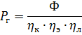
where ηk is the efficiency of the working capacitor, depending on the area of the heat transfer surface, the heat transfer coefficient and the temperature difference between the material and the medium ηk = 0.8 ... 0.9, ηe is the electrical efficiency of the oscillating circuit ηe = 0.65 ... 0 , 7, ηl — efficiency, taking into account losses in high-frequency connecting wires ηl = 0.9 … 0.95.
Power consumed by the generator from the grid:
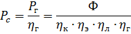
Here ηg is the generator efficiency ηg = 0.65 … 0.85.
The total efficiency of a high-frequency installation is determined by the product of the efficiency of all its units and is equal to 0.3 ... ... 0.5.
Such low efficiency is an important factor that prevents the widespread use of dielectric heating in agricultural production.
The energy performance of high frequency installations can be improved by using the heat dissipated by the generator.
The frequency of the current when heating dielectrics and semiconductors is selected based on the required heat flow F. In the heat treatment of agricultural products, the specific volume flow is limited by the permissible rate of heating and drying. From the balance of forces in the work capacitor we have

where V is the volume of heated material, m3.
The minimum frequency at which the technological process takes place at a given speed:
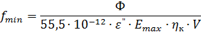
where Emax is the maximum allowable electric field strength in the material, V / m.
As the frequency increases, Em decreases and therefore the reliability of the technological process increases. However, there are some limitations to increasing the frequency. It is impractical to increase the frequency if the loss ratio drops sharply. Also, as the frequency increases, it becomes increasingly difficult to match the parameters of the load and the generator. Maximum frequency, Hz, at which this agreement is provided:
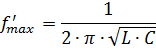
where L and C are the minimum possible equivalent values of inductance and capacitance of the load circuit with a working capacitor.
With large linear dimensions of the working capacitor, an increase in frequency can lead to an uneven distribution of voltage on the electrode and, therefore, to uneven heating. The maximum allowable frequency, Hz, for this condition
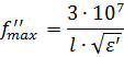
where l is the largest plate size of the working capacitor, m.