Sources and networks of direct working current
 In substations for powering working circuits direct current usually acid batteries (stationary and portable) and in some cases alkaline batteries are used. Stationary batteries consist of individual batteries, usually connected in series.
A battery is called a secondary chemical current source whose job is to accumulate electrical energy (charge) and return this energy to the user (discharge).
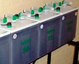
The main parts of the acid battery (Fig. 1) are lead positive 2 and negative 1 plates, connecting lead strips 5, electrolyte, separators 3 and a vessel. Lead plates with a large number of edges are used as positive, which increases the working surface of the plates, as negative - box-type plates. After the formation of the positive plates, lead dioxide PbO2 is formed, and on the negative plates, sponge lead Pb is formed.
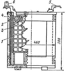
Rice. 1. Accumulators type SK -24 in a wooden container: 1 — negative plate, 2 — positive plate, 3 — separator, 4 — retaining glass, 5 — connecting strip, 6 — tip of the branch
The electrolyte consists of high purity sulfuric acid and distilled water.The density of the electrolyte of a stationary charged battery at 25 ° C is 1.21 g / cm3.
Between the positive and negative plates of the battery, insulating partitions are installed - separators that prevent the plates from closing in case of possible distortion and the active mass falling out of them.
The battery is characterized by capacity, EMF, charging and discharging currents. The nominal capacity of the battery (in ampere-hours) is its capacity at a 10-hour discharge and normal temperature (25 ° C) and density (1.21 g / cm3) of the electrolyte.
In substations, mainly 220 V batteries are used, assembled from C, SK, SN batteries.
C (stationary) batteries are designed for discharges of 3 to 10 hours or more. CK batteries (stationary for short-term discharge modes) allow discharge for 1-2 hours, therefore, in CK batteries, reinforced connecting strips are used between the plates, designed for high current.
C and CK battery vessels are open, for rooms C -16, CK -16 and smaller - glass, and for large rooms - wooden, lined with lead (or ceramic) inside. CH-type accumulators are characterized by the fact that they are placed in sealed closed containers. These batteries have relatively small weight and dimensions, they can be installed in one room with other electrical equipment.
The battery number (after the letter designation) characterizes its capacity. The ampere-hour capacity is equal to the number of batteries multiplied by the unit capacity of an individual battery with the number number 1. For batteries of types C-1 and SK-1, this capacity is 36 Ah, and for types C-10 and SK - 10 — 360 Ah.
In small substations, in the absence of significant inrush loads and sharp fluctuations in the network of operating current (when the switches are turned on, etc.), portable starter batteries of small capacity with a voltage of 24 and 48 V are used. In such substations, the battery it usually works for a long time in a normal discharge mode and after a certain time — after losing its nominal capacity (which is determined by control measurements of the battery voltage) — it is replaced by a spare one. Alkaline batteries are sometimes used, in which an aqueous solution of caustic potassium with a density of 1.19-1.21 g / cm3 serves as the electrolyte.
In the positive plates of alkaline batteries, the active substance is nickel oxide hydrate, and in the negative plates - cadmium with an admixture of iron (nickel-cadmium batteries) or only iron (nickel-iron batteries). At substations, iron-nickel batteries of elements of the NZh and TNZh types are most often used.
Lead and alkaline batteries have their advantages and disadvantages: lead-acid batteries have higher discharge voltages (1.8-2 and 1.1-1.3 V) than alkaline batteries, greater capacity and energy efficiency. Therefore, when making up a battery of the same voltage, lead-acid batteries require almost half as much. The characteristics of alkaline batteries are compactness, density, mechanical strength, low self-discharge and the ability to work at low temperatures.
Rechargeable batteries are the most reliable power source for secondary devices, as they provide independent (autonomous) power supply to operating circuits in the event of an AC voltage failure.
In emergency mode, the batteries take over the load of all DC consumers, providing relay protection and automation, as well as the ability to turn on and off switches... The limiting duration of the emergency mode is assumed equal to 0.5 h for all electric receivers and working circuits with direct current, and for communication and telemechanics 1-2 hours., 0 h).
The use of rechargeable batteries is limited due to their high cost and complexity of operation. Therefore, they are installed in the largest substations. In substations of 500 kV and above, two or more batteries are installed.
Currently, static rectifiers called battery chargers are used to charge batteries. In the old substations, a significant number of engine generators are still in operation.
During operation, the electrical energy stored in the battery is continuously consumed. To replenish it, rechargeable devices are used, which can also be used as motor generators and static rectifiers. The power of the chargers is usually 20-25% of the power of the chargers. In some cases, the same device can perform the functions of a charging and recharging device.
Motor generators consist of an induction motor and a DC generator with parallel excitation. Both machines are mounted on the same frame, and their shafts are connected by an elastic coupling. When charging the battery, the generator voltage of the charger must change, therefore the DC generator is selected with a wide range voltage regulation by changing its excitation with a shunt rheostat.Silicon rectifiers are widely used as static charging and recharging devices.
Unlike the motor-generator, static rectifiers are cheaper, have no moving parts, are more convenient to maintain, have a long service life and a large overload capacity, and therefore are the most common.
The distribution of direct current, the connection of the charging and recharge-charge devices to the storage battery is carried out through the direct current circuit boards (DCB), on which the switching equipment and instruments are located. For the convenience of the actions of the personnel on duty, DC DC mnemonic circuits are applied to the DCS.
Batteries, DC power supplies, charging and recharging devices, DC electrical receivers are connected to each other by cable lines and in some cases by busbars. Together they form an electrical circuit for the DC network.
There are three main modes of operation of rechargeable batteries: jet charging, charge-discharge and charge-rest-discharge.
In substations, batteries are usually operated in trickle charging mode... In this case, the recharger equipped with a voltage stabilization device (with an accuracy of ± 2%) always supplies the constantly switched-on electrical receivers of the network for operating current (signal lamps, relays coils, contactors), and also recharges the battery, compensating for its self-discharge.
As a result, the battery is fully charged at all times. Short-term load shocks are mainly absorbed by the battery.
In fig. 2 shows a diagram of the battery installation at a 500 kV substation.The substation has two storage batteries and three recharging and charging devices, one of which is spare. Accumulator batteries are assembled from SK-type lead-acid batteries used as charging and recharging devices semiconductor rectifiers VAZP-380 / 260-40 / 80... The DC board is assembled from complete DC panels of the PSN-1200-71 series.
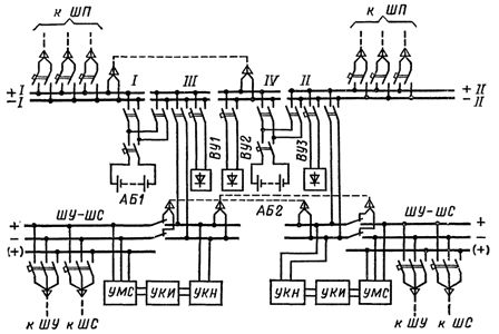
Rice. 2. Schematic diagram of the battery installation without additional elements: AB1, AB2 — storage batteries, VU1, VU2, VUZ — rectifier devices, UMC — flashing light device, UKN — voltage level control device, UKI — control device insulation, SH — control bus, SH — signal buses, (+) — flashing buses, I, II, III, IV — section numbers, SH — power buses of electromagnets for switching on switches
Shield tires are divided into two main (I and II) and two auxiliary (III and IV) sections. Electrical receivers are powered by sections I or II, auxiliary sections are used for mutual shorting of power sources: storage batteries and rectifiers for charging and recharging.
Electrical receivers and power supplies are connected using automatic switches of the A3700 and AK-63 series. These switches perform the functions of switching devices and protect the DCB connections from short circuits. The board is equipped with devices for flashing light UMC, insulation control UCI and voltage level UCN.
In installations where increased voltage is required to turn on powerful electromagnets of oil switches, additional elements are installed. Batteries with extra cells consist of 120, 128, 140 cells instead of 108.In such cases, the circuit changes somewhat.
To prevent sulphation of the plates of additional cells, an adjustable resistor is connected between the negative pole and the branches of the 108th cell, with the help of which a discharge current equal to the discharge current of the main cells is created. This guarantees the same operating conditions for the main and additional cells and excludes the possibility of deep charges and discharges, which prevents sulphation and increases the service life of the batteries. In trickle charge mode, the battery is always in a charged state and ready to supply users with direct current.
In normal mode, the voltage of each switched-on battery cell should be 2.2 V with a tolerance of ± 2%. In cases where direct current of different voltages is required to power the secondary devices, portable batteries and branches from the intermediate battery cells are used.
For example, for most relay protection devices a voltage of 220 V is required, for telemechanical devices 24, 48 or 60 V and for powering powerful electromagnetic drives of oil switches - a voltage of up to 250 V and more to compensate for the voltage drop in the cable from the battery to the switchgear, where the switches are installed at high inrush currents.
In some installations, the storage batteries operate in charge-discharge mode. In this case, the voltage at the battery terminals does not remain constant, but varies in a relatively wide range (for lead-acid batteries, during discharge, the voltage changes from 2 to 1.8-1.75 V, and when charging from 2, 1 to 2,6 -2, 7 B).
To maintain a stable battery voltage level in all modes of the DC busses of the DC board in the battery circuits operating by the charge-discharge method, an element switch is provided, which serves to change the number of batteries connected to the busses of the installation or to the charger.
The operation of battery installations in the charge-rest-discharge mode is not considered here, since this mode is not used in substations.
Batteries with a voltage of 24, 36 or 48 V usually consist of several portable batteries that are connected in series. In most cases, two sets of such batteries are installed, one of which is spare.