Installations for ultrasonic cleaning of parts
Application of ultrasound
 Ultrasound used for washing parts and assemblies of various equipment, welding various materials. Ultrasound is used to produce suspensions, liquid aerosols and emulsions. To obtain emulsions, for example, a mixer-emulsifier UGS-10 and other devices are produced. Methods based on the reflection of ultrasonic waves from the interface between two media are used in devices for hydrolocalization, defect detection, medical diagnostics, etc.
Among the other capabilities of ultrasound, it should be noted its ability to process hard brittle materials to a given size. In particular, ultrasonic processing is very effective in the production of parts and holes with complex shapes in products such as glass, ceramics, diamond, germanium, silicon, etc., whose processing is difficult by other methods.
The use of ultrasound in the restoration of worn parts reduces the porosity of the applied metal and increases its strength. In addition, distortion of elongated welded parts such as engine crankshafts is reduced.
Ultrasonic cleaning of parts
Ultrasonic cleaning of parts or objects is used before repair, assembly, painting, chrome plating and other operations. Its use is particularly effective for cleaning parts with a complex shape and hard-to-reach places in the form of narrow slots, slots, small holes, etc.
The industry produces a large number of ultrasonic cleaning devices that differ in design features, capacity and power of the bath, for example, transistor: UZU-0.25 with an output power of 0.25 kW, UZG-10-1.6 with a power of 1.6 kW , etc., thyristor UZG-2-4 with an output power of 4 kW and UZG-1-10 / 22 with a power of 10 kW. The operating frequency of the installations is 18 and 22 kHz.
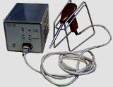
The ultrasonic unit UZU-0.25 is designed for cleaning small parts. It consists of an ultrasonic generator and an ultrasonic bath.
Technical data of the ultrasonic unit UZU-0.25
-
Mains frequency — 50 Hz
-
Consumed power from the network — no more than 0.45 kVA
-
Operating frequency — 18 kHz
-
Output power — 0.25 kW
-
Internal dimensions of the work tub — 200 x 168 mm with a depth of 158 mm
On the front panel of the ultrasonic generator there is a switch for turning on the generator and a lamp indicating the presence of supply voltage.
On the rear wall of the generator chassis there are: a fuse holder and two connectors through which the generator is connected to the ultrasonic bath and the electrical network, a terminal for grounding the generator.
Three packaged piezoelectric transducers are mounted in the bottom of the ultrasonic bath.The single-transducer package consists of two piezoelectric plates made of TsTS-19 (lead zirconate-titanate) material, two frequency-reducing pads and a central stainless steel rod, the head of which is the radiating element of the transducer.
On the body of the bath there is: a fitting, a faucet handle marked "Drain", a terminal for grounding the bath and a plug connector for connection to a generator.
Figure 1 shows the circuit diagram of the ultrasonic unit UZU-0.25.
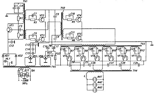
Rice. 1. Schematic diagram of the ultrasonic unit UZU-0.25
The first stage is master oscillatoroperating on transistor VT1 according to a circuit with inductive feedback and an oscillating circuit.
Electrical vibrations with an ultrasonic frequency of 18 kHz, occurring in the main oscillator, are fed to the input of the powerful preamplifier.
The pre-power amplifier consists of two stages, one of which is assembled on transistors VT2, VT3, the second - on transistors VT4, VT5. Both power preamplification stages are assembled according to a sequential push-pull circuit operating in switching mode. The key mode of operation of transistors allows obtaining high efficiency at sufficiently high power.
Basic circuits of transistors VT2, VT3. VT4, VT5 are connected to separate, opposite windings of transformers TV1 and TV2. This provides push operation of the transistors, that is, alternate switching.
Automatic biasing of these transistors is provided by resistors R3 — R6 and capacitors C6, C7 and C10, C11 included in the main circuit of each transistor.
The alternating excitation voltage is supplied to the base through the capacitors C6, C7 and C10, C11, and the constant component of the base current, passing through the resistors R3 — R6, creates a voltage drop on them, which ensures reliable closing and opening of the transistors.
The fourth stage is the power amplifier. It consists of three push-pull cells of transistors VT6 — VT11 operating in switching mode. The voltage from the preamplifier is supplied to each transistor from a separate winding of the transformer TV3, and in each cell these voltages are antiphase. From the transistor cells, the alternating voltage is applied to the three windings of the TV4 transformer, where the power is added.
From the output transformer, the voltage is supplied to the piezoelectric transducers AA1, AA2 and AAZ.
Since the transistors operate in switching mode, the output voltage containing harmonics is square-wave. To isolate the first harmonic of the voltage of the converters, the coil L is connected in series with the converters to the output winding of the transformer TV4, the inductance of which is calculated in such a way that with the own capacitance of the converters it forms an oscillating circuit tuned to the 1st harmonic of the tension. This makes it possible to obtain a sinusoidal voltage in the load without changing the energy favorable mode of the transistors.
The installation is powered by alternating current with a voltage of 220 V at a frequency of 50 Hz using a power transformer TV5, which has a primary winding and three secondary windings, one of which serves to power the main generator, and the other two serve to power the other stages.
The main generator is fed by a rectifier assembled according to two-loop circuit with zero point (diodes VD1 and VD2).
The power supply of the preliminary amplification stages is carried out by a rectifier assembled in a bridge circuit (diodes VD3 — VD6). The second bridge circuit of diodes VD7 — VD10 supplies power to the power amplifier.
A cleaning medium should be selected depending on the nature of the contamination and the materials. If trisodium phosphate is not available, soda ash can be used to clean steel parts.
Cleaning time in an ultrasonic bath varies from 0.5 to 3 minutes. The maximum permissible temperature of the cleaning medium is 90 °C.
Before changing the wash fluid, the generator must be turned off, preventing the converters from operating without fluid in the tub.
The cleaning of parts in an ultrasonic bath is carried out in the following sequence: the power switch is set to the «Off» position, the drain valve of the bath is set to the «Closed» position, the cleaning medium is poured into the ultrasonic bath to a level of 120 — 130 mm, the plug of the power cord is plugged into a 220 V electrical outlet.
Testing the installation: turn the switch to the "On" position until the signal lamp should light up and the working sound of cavitating liquid should appear. The appearance of cavitation can also be judged by the formation of the smallest mobile bubbles on the bath probe.
After testing the installation, disconnect it from the mains, load the contaminated parts into the bath and start the treatment.