Electrical equipment of a mine electric resistance furnace SShOD
The mine laboratory electric furnace with indirect heating SSHOD-1.1,6 / 12-MZ-U4.2 is designed for melting and heat treatment of various materials at temperatures up to 1100 ° C in stationary laboratories. The furnace has the following parameters:
-
energy consumption during heating — 2.5 kW;
-
power consumption to maintain the working temperature — 1.5 kW;
-
nominal working temperature — 1100 ° C;
-
heating time to the nominal operating temperature of the unloaded furnace -150 minutes;
-
uneven temperature in the working space at the nominal temperature of the unloaded furnace — 5 ° C;
-
accuracy of automatic regulation at nominal temperature — 2 ° С.
The electric resistance furnace SSHOD-1.1,6 / 12-MZ-U4.2 is a rectangular housing made of sheet metal, in which a heating chamber and a control unit are located (Fig. 1).
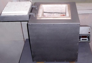
Rice. 1. The design of the electric furnace
The heater is made in the form of a ceramic tube, on which an alloy wire with high resistance… The inner surface of the heating tube forms the working space of the electric furnace.
The control unit of the electric furnace is used to automatically maintain the set temperature with an accuracy specified in the technical specification.
The elements of the control unit — a regulating millivoltmeter 5, an electronic attachment, a thyristor, a signal lamp 6 and a switch are located on the front panel 8, which is attached to the side walls of the housing of the heating chamber with four screws 9 To reduce heat loss through the opening of the working chamber, the latter is closed with cover 10.
The functional diagram of the electric furnace is shown in fig. 2.
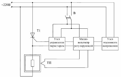
Rice. 2. Functional diagram of a shaft laboratory furnace
To the power rails are connected directly or through a switch: an electric furnace in series with a thyristor, a thyristor control unit, a regulating millivoltmeter and a reference voltage unit.
The thyristor functions as a proximity switch. The measurement and control of the temperature is carried out using a thermocouple Tp and a regulating millivoltmeter.
The thyristor control unit is designed to generate control signals that are entered into the thyristor control circuit by commands from the regulating millivoltmeter.
The voltage reference node is used to generate the reference voltage required for the operation of the regulating millivoltmeter.
Schematic diagram of a shaft laboratory furnace
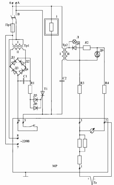
Rice. 3. Schematic circuit diagram of the resistance of an electric furnace SShOD-1.1-1.6 / 12-M3-U4.2
The electric furnace 1 through the thyristor T1 is connected directly to the input busbars of the 220 V power supply.The thyristor control unit is made on the basis of the transformer Tp1, the rectifier bridge of diodes D1-D4, capacitor C1, resistor R1 and diodes D5, D6.
The regulating millivoltmeter consists of the millivoltmeter itself, included in the diagonal of the bridge formed by the thermocouple Tp, resistors R2-R7 and the node of the reference voltage. Opening contacts installed on the temperature setting mechanism are connected to terminals 5, 6. These contacts are opened by a limiter connected to the arrow of the millivoltmeter.
The node of the reference voltage is made on the transformer Tr2, in the primary winding of which the current-limiting capacitor C2 is included, and in the secondary - the diode rectifier D8. Resistor R2 is a current limiting resistor and serves to set the operating point of the zener diode D9. The voltage taken by the zener diode is the output for the reference voltage node.
Working according to the scheme of a mining laboratory furnace with electric resistance
When the switch B is turned off (see Fig. 3), a voltage of 220 V is supplied to the furnace terminals. The set temperature indicator is set to the required value. Thyristor T1 is locked because no current flows in the circuit of its control electrode. The oven does not heat up.
When the switch B is turned on, the thyristor is unlocked, because the current begins to flow through its control electrode through the circuit: cathodes of diodes D1, D3 — resistor R1 — diodes D5, D6 — control electrode of thyristor T1 — cathode of thyristor T1 — opening contact of the regulating millivoltmeter — anodes of diodes D2, D4. The oven starts to heat up.
At time t1, the opening contact of the regulating millivoltmeter breaks the target of the gate of the thyristor T1.The thyristor is locked and the oven is turned off. The temperature is starting to drop. At time t2, the electric furnace is switched on and its temperature begins to rise. As a result, the temperature of the electric furnace fluctuates around the set value, as shown in fig. 4.
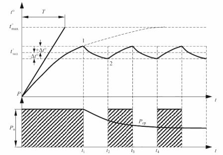
Rice. 4. Dependences on the temperature and energy consumption of the electric furnace over time