How an induction heater works and works
The principle of operation of an induction heater consists in heating an electrically conductive metal workpiece by means of a closed eddy current induced in it.
Eddy currents are currents that arise in solid wires due to the phenomenon of electromagnetic induction when these wires are penetrated by an alternating magnetic field. Energy is used to create these currents, which is converted into heat and heats up the wires.
To reduce these losses and eliminate heating, instead of solid wires, layered wires are used, in which the individual layers are separated by insulation. This isolation prevents the occurrence of large closed eddy currents and reduces the energy losses to maintain them. It is for these reasons that transformer cores, armatures of generators, etc., are made of thin steel sheets insulated from each other by layers of varnish.
The inductor in an induction heater is an alternating current coil designed to create a high frequency alternating electromagnetic field.
The alternating high-frequency magnetic field, in turn, acts on an electrically conductive material, causing a closed current of high density in it and thus heating the workpiece until it melts. This phenomenon has been known for a long time and has been explained since the time of Michael Faraday, who described phenomenon of electromagnetic induction back in 1931
The time-varying magnetic field induces an alternating EMF in the conductor, which intersects with its lines of force. Such a wire can generally be a transformer winding, a transformer core, or a solid piece of some metal.
If the EMF is induced in the coil, then a transformer or receiver is produced, and if directly in the magnetic circuit or in a short circuit, induction heating of the magnetic circuit or coil is produced.
In a poorly designed transformer, for example, core heating by Foucault currents would be unequivocally harmful, but in an induction heater such a phenomenon serves a useful purpose.
From the point of view of the nature of the load, an induction heater with a conductive part heated in it is like a transformer with a short-circuited secondary winding of one turn. Since the resistance inside the workpiece is extremely small, even a small induced eddy electric field is sufficient to create a current of such high density that its thermal effect (cf. The Joule-Lenz law) would be very expressive and practical.
The first channel furnace of this type appeared in Sweden in 1900, it was fed with current with a frequency of 50-60 Hz, it was used to melt steel channel and the metal was fed into a crucible arranged in a short-chain rotation manner of the secondary winding of a transformer.The efficiency problem was of course present as the efficiency was less than 50%.
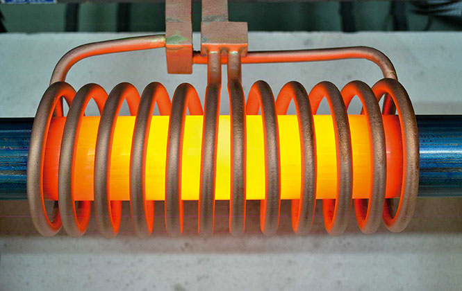
Today, an induction heater is a wireless transformer consisting of one or more turns of a relatively thick copper tube through which the coolant of an active cooling system is pumped using a pump. An alternating current with a frequency of several kilohertz to several megahertz is applied to the conductive body of the tube, like an inductor, depending on the parameters of the sample being processed.
The fact is that at high frequencies the eddy current is displaced from the sample heated by the eddy current itself, because the magnetic field of this eddy current displaces the current that was generated towards the surface.
This manifests as skin effect, when the maximum current density is the result of the workpiece surface falling on a thin layer, and the higher the frequency and the lower the electrical resistance of the heated material, the thinner the shell layer.
For copper, for example, at 2 MHz, the skin is only a quarter of a millimeter! This means that the inner layers of the copper billet are heated not directly by eddy currents, but by heat conduction from its thin outer layer. However, the technology is efficient enough to rapidly heat or melt almost any electrically conductive material.
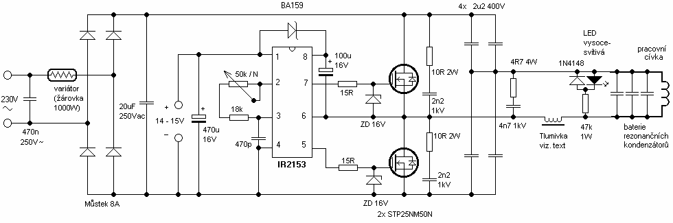
Modern induction heaters are being built based on an oscillating circuit (coil-inductor and capacitor) powered by an included resonant inverter IGBT or MOSFET — transistorsallowing to achieve operating frequencies up to 300 kHz.
For higher frequencies, vacuum tubes are used, which make it possible to reach frequencies of 50 MHz and higher, for example, for melting jewelry, quite high frequencies are required, since the size of the part is very small.
To increase the quality factor of the working circuits, they resort to one of two ways: either increasing the frequency or increasing the inductance of the circuit by adding ferromagnetic inserts to its construction.
Dielectric heating is also carried out using a high-frequency electric field in industry. The difference from induction heating is the current frequencies used (up to 500 kHz with induction heating and more than 1000 kHz with dielectric). In this case, it is important that the substance to be heated does not conduct electricity well, i.e. was a dielectric.
The advantage of the method is the generation of heat directly inside the substance. In this case, poorly conductive substances can quickly heat up from the inside. For more details see here: Fundamental physical foundations of high-frequency dielectric heating methods