How to measure direct current and voltage
The measurement of direct current and voltage is most often carried out by magnetoelectric panel meters, and when measuring high voltage - by electrostatic and ion systems. Devices from electromagnetic, electrodynamic and ferrodynamic systems are sometimes used, they are significantly inferior to devices of the magnetoelectric system in terms of accuracy, sensitivity, power consumption, have an uneven scale and are sensitive to the effects of external magnetic fields. Digital voltmeters, ammeters and combination devices with high speed and low measurement error (0.01-0.1%) are increasingly used for accurate measurements.
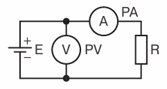
 The simplest way to measure direct current and voltage is the direct inclusion of devices in the circuit, which is possible when the following conditions are met:
1) the maximum measurement limit of the ammeter (voltmeter) is not less than the maximum current (voltage) in the circuit;
2) the nominal voltage of the ammeter is not less than the nominal voltage in the network;
3) the resistance of the ammeter Ra is much less, and the resistance of the voltmeter is much higher than the resistance of the measured circuit Rn, the significant resistance of the ammeter reduces the current in the circuit when it is turned on by an amount
4) compliance with the polarity when turning on the devices.
To extend the measurement limits of devices, transducers are used in the form measuring shunts, additional resistances, voltage dividers, measuring transformers and measuring amplifiers. A shunt is a resistance connected in parallel with the measuring device in the circuit of the measured current.
Usually, shunts are installed inside the device for currents up to 50-100 A. For large currents, external shunts are used, which have current clamps for connecting the measured current to the circuit and potential clamps for connecting a measuring device. In order to unify measuring devices, shunts are manufactured in accordance with GOST 8042-78 Accuracy class shunts 0.05-0.5.
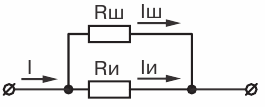
By connecting a millivoltmeter to the shunt with a measurement limit corresponding to the nominal voltage drop across the shunt, we obtain the full scale of the device up to the nominal shunt current. Measured current

where In, Un — nominal shunt current and shunt voltage drop; U -millivoltmeter readings.
To extend the measurement limits of voltmeters, an additional resistance Rd is included in series with the measuring device.
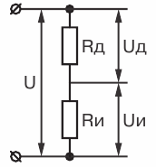
Measured voltage
where P = Rd / Rc + 1 — coefficient of expansion of the measurement limit of the device; Uv — voltmeter reading;
Rv is the input resistance of the voltmeter.
Additional resistances can be both internal (placed in the device case) and external for measuring voltages above 500 V.
 The nominal currents of additional resistances are standardized by GOST 8623-78 at the nominal voltage drop across them. Basic error of additional resistances ± (0.1-0.5)%. To extend the measurement limits of devices with high input resistance, voltage dividers with a fixed division ratio, usually a multiple of 10, are used. In high-voltage power transmission installations and in high-current circuits, in addition to those specified converters . DC measuring transformers can be used.