How to measure power in a three-phase AC circuit
Power in a three-phase circuit can be measured using one, two and three wattmeters. The single-device method is used in a three-phase symmetrical system. The active power of the entire system is equal to three times the energy consumption in one of the phases.
When connecting the load in star with an accessible neutral point, or if, when connecting the load in delta, it is possible to connect the wattmeter coil in series with the load, you can use the switching circuits shown in fig. 1.
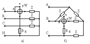
Rice. 1 Circuits for measuring the power of three-phase alternating current when connecting loads a — according to a star circuit with an accessible zero point; b — according to the triangle scheme, using one wattmeter
If the load is star connected with an unavailable neutral point or delta, then a circuit with an artificial neutral point can be used (Fig. 2). In this case, the resistances must be equal to Rw + Ra = Rb = Rc.
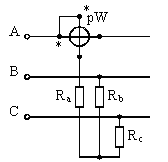
Figure 2. Three-phase AC power measurement scheme with one wattmeter with an artificial zero point
 To measure the reactive power, the current ends of the wattmeter are connected to the section of each phase, and the ends of the voltage coil to two other phases (Fig. 3). Full reactive power is determined by multiplying the wattmeter reading by the root of three. (Even with a slight phase asymmetry, using this method gives a significant error).

Rice. 3. Scheme for measuring the reactive power of three-phase alternating current with one wattmeter
 The two-device method can be used with balanced and unbalanced phase loading. Three equivalent options for including wattmeters for measuring active power are shown in fig. 4. Active power is determined as the sum of the wattmeter readings.
When measuring reactive power, the circuit of Fig. 5, but with an artificial zero point. To create a zero point, it is necessary to fulfill the condition of equality of the resistances of the voltage windings of the wattmeters and the resistor R. The reactive power is calculated by the formula

where P1 and P2 — readings of wattmeters.
Using the same formula, you can calculate the reactive power with uniform loading of the phases and connection of wattmeters according to the diagram in fig. 4. The advantage of this method is that active and reactive power can be determined using the same scheme. With uniform loading of the phases, the reactive power can be measured according to the diagram in fig. 5 B.
The three-part method applies to each phase load. The active power can be measured according to the diagram in fig. 6. The power of the entire circuit is determined by summing the readings of all wattmeters.
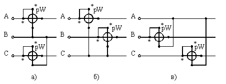
Rice. 4.Schemes for measuring the active power of three-phase alternating current with two wattmeters a — the current windings are included in phases A and C; b — in phases A and B; c — in phases B and C
The reactive power for a three- and four-wire network is measured according to the diagram in fig. 7 and is calculated by the formula

where РА, РБ, РК — readings of wattmeters included in phases A, B, C.
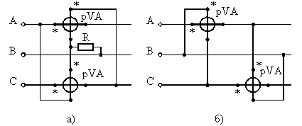
Rice. 5. Schemes for measuring reactive power of three-phase alternating current with two wattmeters
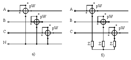
Rice. 6. Schemes for measuring the active power of three-phase alternating current with three wattmeters a — in the presence of a neutral conductor; b — with an artificial zero point
In practice, one-, two- and three-element three-phase wattmeters are usually used according to the measurement method.
To expand the measurement limit, you can apply all the indicated schemes when connecting wattmeters through current and voltage measuring transformers. In fig. 8 shows as an example a scheme for measuring power by the method of two devices when they are switched on by current and voltage measuring transformers.
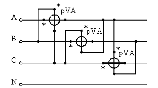
Rice. 7. Schemes for measuring reactive power with three wattmeters
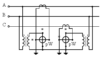
Rice. 8. Schemes for switching on wattmeters through measuring transformers.
