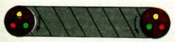
Checking the phase rotation of the power cables
Simple ways to phase the cable
The simplest way to find current-carrying wires at the end of the cable corresponding to certain phases from its beginning is to check "gathering" of cable cores using telephone handsets, for example, when checking power cables laid between different premises of stations and substations. The wiring diagram for the handset is shown in Figure 1.
As one of the wires for establishing communication, grounded structures (grounded metal sheath of the cable) are used, to which telephone handsets are connected. In addition, on one side of the cable, the wire from the battery is connected to the current-carrying core (for example, phase C).
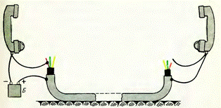
Wiring diagram for telephone handsets when phasing the cable
On the other side of the cable, with the second wire from the earpiece, they alternately touch the current-carrying wires, each time giving a voice signal to the earpiece.After finding the vein for which reviewer feedback will be obtained, it is marked as phase C and the search for other veins continues in the same order. Instead of ordinary headphones, it is recommended to use headphones, the use of which frees the inspectors' hands for work.
To check the phase sequence, it is widely used megohmmeter, the connection diagram of which is shown in Figure 2. For this, the conductors are grounded in series at the beginning of the cable, and at the end the insulation resistance of the conductors is measured relative to the ground.
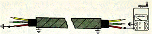
Wire phasing megohmmeter wiring diagram
A grounded wire is detected by the readings of a megohmmeter, since the resistance of its insulation to the ground will be zero, and the other two wires will be tens and even hundreds of megohms.
With this test method, the grounding is installed and removed three times. In addition, personnel at the ends of the cable must communicate with each other to coordinate their actions. All this refers to the disadvantages of this verification method.
A more advanced method of phasing the cable is the measurement method according to the scheme shown in Figure 3.
One of the three cores of the cable (let's call it phase A) is firmly connected to the grounded sheath, the other core (phase C) is grounded through a resistance of 8-10 megohms. A tube with resistors is usually used as resistance pointer UVNF… The third core (phase B) is not grounded, it remains free. At the other end of the cable, a megohmmeter is used to measure the resistance of the wires to ground.
Obviously, phase A will correspond to a wire whose resistance to earth is zero, phase C to a wire with an earth resistance of 8-10 megohms, and phase B to an infinitely high resistance wire.
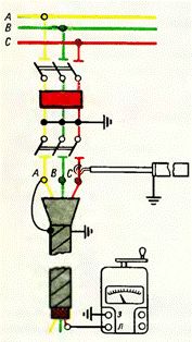
Connection diagram of a megohmmeter and an additional resistor when phasing the cable
Safety in the production of phase cables
 According to safety conditions, during the production of phase cables, phasing is carried out only on a cable line disconnected from all sides. In this case, measures must be taken against the supply of operating voltage to the cable. Before starting step-by-step use of a megohmmeter, all personnel near the cable are warned not to touch live wires.
The connecting wires from the megometer must have reinforced insulation (for example, PVL type wire). They are connected to the current-carrying wires after the cable is discharged from the capacitive current. To remove the residual charge, the cable is grounded for 2-3 minutes.
Checking the phase rotation of the power cables by the color of the core insulation
The current-carrying conductors of power cables with impregnated paper insulation are colored with colored paper strips wound over their insulation. One of the wires, as a rule, is surrounded by red tape, the other with blue, and the insulation of the third is not specially colored - it retains the color of the cable paper.
In the production of cables, the cores are twisted together so that during one step of the twisting, each core changes its position in the cross-sectional area, making one revolution around the axis of the cable.By looking at the cross-sectional areas at both ends of the cable, you can find that, relative to the observer, the phases in the cross-sections alternate in different directions. These design features of the cables are taken into account when phasing and connecting the core.
Phase rotation in cable cross-sections. The arrows indicate the directions of the phase bypass.
Suppose it is necessary to phase and connect the conductors at both ends of a three-phase cable. Phasing in this case is elementary simple. It consists in the fact that pairs of the same color are selected from six cores. These veins are noted and prepared for ligation. For the connection, it is necessary that the axes of the wires of the same color coincide, and the direction of rotation of the phase in the cross-sectional area of one end of the cable is a mirror image of the other.
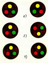
Some options for alternating colored wires in the sections of two cables: a — it is possible to connect wires of the same color; b — the same after rotating the section by 180 °; c — the connection of three veins by their colors is impossible.
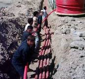 At laying cables in a trench the probability of coincidence of vein axes is small. Most often, the phases of one color a turn out to be rotated relative to each other at some angle, the value of which can reach 180 °.
During assembly (or repair), cables with mismatched axes of the same colored cores are twisted around the axis until the exact match of the core axes is recorded. However, strong twisting is not safe. It causes mechanical stresses in the protective and insulating covers of the cables and leads to a decrease in operational reliability.
In order for all connected cores to match in color, the directions of the phase alternations in the cross sections of the cable must be opposite. This is checked in advance, before laying the cable in the trench, if there are no marks at its ends indicating the direction of phase rotation. Note that for phase-rotation cables directed in one direction, only one core matches in color, and the other two cannot match.
The advantage of the method of connecting cables with the same colored wires is that phasing here is not an independent operation, it is carried out during the work itself, and the process of laying, repairing and operating cables acquires a more harmonious system and requires less labor.
Checking the phase rotation of power cables with the FK-80 device
For phasing, two emitters are superimposed on two cores of the cable at its supply end: on phase A — emitter of continuous signal I1, on phase B — emitter of intermittent signal I2, phase C remains free. Grounding not removed from the cable line — does not interfere with phasing. During phasing or long before, the FK-80 device is connected to the 220 V network. The emitters induce the corresponding EMF in the cable cores. At the other end of the line, the telephone handset is connected by one wire to ground (earthed cable sheath) and the other wire is in series with the current-carrying conductors of the cable.
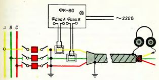
Application of the FK-80 cable phasing device
The belonging of the cable core to one or another phase is determined by the nature of the sound in the headphones.If a continuous signal is heard, the tubes are connected to phase A, an intermittent signal to phase B and no sound will indicate that the tubes are connected to phase C. EMF of audio frequency induced in the cable cores (its value does not exceed 5 V) no is an obstacle for repair work on the cable line.