How to measure the electrical resistance of direct current
Choosing a measurement method depends on the expected measured resistance values and the required accuracy... The main methods for measuring DC resistance are indirect, direct assessment and pavement.

Figure 1. High (a) and low (b) resistance measurement probe schematics

Figure 2. Schemes for measuring large (a) and small (b) resistances ammeter - voltmeter method In the main circuits of the indirect method, voltage and current meters are used.
 Figure 1a shows a circuit suitable for measuring resistances of the same order as the input resistance Rv of the voltmeter Rn. After measuring the voltage U0 with a short circuit Rx, the resistance Rx is determined by the formula Rx = Ri (U0 / Ux-1).
When measuring according to the diagram in fig. 5.1, b high-resistance resistors are connected in series with the meter, and small resistors are connected in parallel.
For the first case, Rx = (Ri + Rd) (Ii / Ix-1), where Ii is the current through the meter when Rx is short-circuited; for the second case

where Ii is the current through the meter in the absence of Rx, Rd is an additional resistor.
The ammeter-voltmeter method is more universal, which makes it possible to measure resistances in certain modes of their operation, which is important when measuring non-linear resistances (see Fig. 2).
For the circuit of Fig. 2, a

Relative methodological error of measurement:

For the circuit of Fig. 2, b

Relative methodological error of measurement:

Ra and Rv are the resistances of the ammeter and voltmeter.
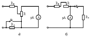
Rice. 3. Circuits of ohmmeters with serial (a) and parallel (b) measuring circuits
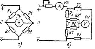
Rice. 4. Bridge circuits for resistance measurement: a — single bridge, b — double.
From the expressions for the relative error, it can be seen that the circuit of Fig. 2, and provides a smaller error when measuring high resistances, and the circuit of fig. 2, b — when measuring small.
The error in the measurement by the ammeter-voltmeter method is calculated by the formula

where gv, g are the accuracy classes of the voltmeter and ammeter; Uп, Iп — measurement limits of voltmeter and ammeter.
Direct measurement of DC resistance is done with ohmmeters. If the resistance values are more than 1 Ohm, ohmmeters with a series measuring circuit are used, and for measuring low resistance, with a parallel circuit. When using an ohmmeter to compensate for changes in supply voltage, it is necessary to install the arrow on the device. For a series circuit, the arrow is set to zero when the measured resistance is manipulated. (Shunting is done, as a rule, with a button specially provided in the device).For a parallel circuit, before starting the measurement, the arrow is set to the «infinity» sign.
To cover the range of low and high resistances, build parallel ohmmeters... In this case there are two Rx reference scales.
The highest accuracy can be achieved using the bridge measurement method. Medium resistances (10 Ohm — 1 MΩ) are measured using a single bridge, and small resistances are measured using a double bridge.
The measured resistance Rx is included in one of the bridge arms, the diagonals of which are connected to the power supply and the zero indicator, respectively; as the latter, a galvanometer, a microammeter with a zero in the middle of the scale, etc., may be used.
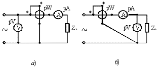
Figure 5. Schemes for measuring large (a) and small (b) alternating current resistances
The equilibrium condition for the two bridges is given by the expression

Arms R1 and R3 are usually implemented in the form of resistance stores (store bridge). R3 sets a range of R3 / R2 ratios, usually multiples of 10, and R1 balances the bridge. The measured resistance is counted according to the value set by the knobs on the resistance boxes. Balancing the bridge can also be done by smoothly changing the ratio of resistors R3 / R2, made in the form of a sliding wire, at a certain value R1 (linear bridge).
 They are used for repeated measurements of the degree of correspondence of resistances with a certain set value Rn unbalanced bridges... They are balanced at Rx = Rн. On the scale of the indicator, you can determine the deviation of Rx from Rn in percent.
On the principle of self-balancing operation automatic bridges... The voltage arising from the imbalance at the ends of the diagonal of the bridge, after amplification, acts on the electric motor, which mixes the sliding wire motor. When balancing the bridge, the motor stops and the position of the slide wire determines a measured resistance value.
Read also: Bridge measurements

