Adjustment of electromagnets and electromagnetic clutches
 Regulation of power electromagnets
Normally, the adjustment of electromagnets is carried out in the following range: external check, Measuring the resistance of a DC coil, measuring the insulation resistance of the coil and sheets of the magnetic circuit, removing the mechanical characteristics and adjusting the installation site.
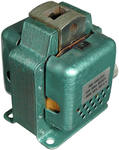
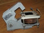
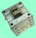
During an external inspection, the condition of the magnetic system is checked, the coil and its wires, whether there is a short circuit (for alternating current electromagnets), a non-magnetic seal (for direct current electromagnets), check the ease of movement of the armature, the reliability of its tight fit to the core of the magnetic system.
The last circumstance is very important, especially for variable electromagnets… It is known that inductance of the coil, is insignificant if the armature is in its initial position and the current in the coil reaches a value that is dangerous for the coil and the contacts of the starter.As the armature is withdrawn, the inductance of the coil increases and the current decreases. When the armature is fully retracted, the current becomes minimal. However, if the armature stops for some reason in an intermediate position, then the amount of current in the coil can be significant and the coil will burn out.
The resistance of the winding to direct current is measured with the same instruments as for other electrical devices and machines.
Inductance of AC electromagnet coils can be measured directly with an RLC bridge or indirectly with an AC ammeter and voltmeter. In this case, the value of the inductance of the coil in H:
where, z = U / I — impedance coils, U — readings of the voltmeter in V, I — reading of the ammeter in A, r — the previously measured resistance of the coil to direct current; is — supply frequency in Hz.
 The insulation resistance of electromagnet coils is measured along with control circuits and other electrically connected devices. The amount of insulation resistance should be at least 0.5 megohm.
Insulation resistance The magnetic circuit sheets of the pullers are checked with a 500 V megohmmeter. The insulation resistance value is not standardized.
 For the correct adjustment of the most critical electromagnets, it is advisable to eliminate the experimental curves of the retracting and opposing forces, depending on the size of the gap.
This is done as follows: remove the counterspring, use a rheostat to set a known current in the coil of the electromagnet, then, placing non-magnetic spacers of a certain thickness between the armature and the core, measure the force that pulls the armature with a dynamometer. Based on the experimental readings, a curve of the electromagnetic force is plotted depending on the size of the gap. The opposing force is removed when the spring is installed and there is no current in the armature coil.
Adjustment of electromagnetic clutches
When checking electromagnetic couplings, it is necessary to measure the leakage of the slip rings, the pressure of the contact brushes, the value of the current in the winding in a steady state. For EMT electromagnetic connectors, slip ring runout shall not exceed 0.02 mm for size 5 - 12 connectors and 0.03 mm for size 13 - 15 connectors.
It is very difficult to check the pressing force of the contact brushes, therefore the value of the contact resistance between the brush and the ring is monitored at different positions of the slip ring. Average measured value contact resistance should not differ from the minimum and maximum measured values by more than 10%. Otherwise, replace the brush or grind the ring.