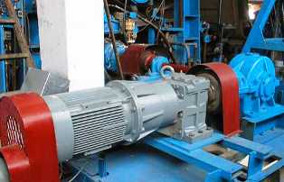
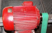
Regulation of electric drives with relay-contactor control
 For commissioning, you need: schematic diagrams, external connection diagrams, assembly and schematic diagrams of plants - manufacturers of consoles, panels, cabinets, power supply diagrams, diagrams of electrical and technological equipment, explanatory note with technological requirements for the electric drive and calculating security settings and operating modes...
1. Getting to know the project:
a) study the functions of the electric drive as part of the technological unit, the technological requirements for the electric drive, the layout of the mechanism, control panels, panels, cabinets, etc.,
b) analyzes the operation of the electric drive according to the schematic diagram, checks compliance with the necessary sequence in the operation of the equipment, the absence of false and bypass circuits, compliance with all technological requirements, the presence of the necessary protections and technological interlocks, identification of errors in the circuit,
c) make verification calculations for the selection of protective settings and functional relays, check the selectivity of protection, calculations for the breakdown of starting and other resistors, the resistance values of the resistors are recorded on the schematic diagram,
d) checks the conformity of the applied equipment with the accepted values of power and working voltage, the conformity of the capabilities of the accepted types of relays with the specified settings,
e) compile a table with settings of protective and functional relays,
f) in accordance with the schematic diagram, check the electrical diagrams of panels, cabinets, consoles, the presence and correctness of the marking on the schematic diagram, compliance with its marking on the electrical diagram,
g) based on the wiring diagrams in the installer's workbook, all external connections related to this electric drive are tabulated.
h) draw up a complete single-line power supply diagram of the electric drive with all types of voltage from sources (distribution box, transformer substation, switch cabinet, main line, etc.) to each connection (cabinet, switchboard, panel),
i) preparation of a commissioning program, clarification of work methods, selection of commissioning protocol forms to be completed in the process of carrying out work.
2. Verification by external inspection of the condition of the electrical equipment, the quality of the performed audit, the quality and volume of the performed electrical installation works (comparing the number of laid cables with the required number according to the table of external connections).
3.Checking the compliance of the installed electrical equipment with the project, certification of the electrical machine, resistors and other devices, the parameters of which must be entered in the commissioning protocol.
4 Inspection and testing of electrical machines.
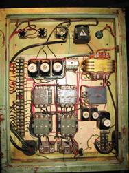 5. Checking the conformity of the installation of internal connections of panels, consoles, cabinets to the schematic diagram.
Before inspection, to remove bypass circuits, disconnect all external connections of the secondary switching circuits of the terminal blocks. The inspection is carried out using a probe. Start checking the circuit of the cabinet, panel, console from the circuits of the poles (phases) of the source of operating current, then check the individual circuits.
They check all the wires from pin to pin and to the terminal block and at the same time they must count the number of wires on each pin to identify unnecessary wires and connections that are not reflected in the schematic diagram. Any redundant wires that may be powered must be disconnected from both sides. When checking, carefully control and correct, if necessary, the marking of circuits on the circuit diagram.
In the process of checking the internal connections, the operation of the actuating and breaking contacts of the relays and contactors is checked by pressing and releasing their armatures, if necessary, the auxiliary contacts are cleaned, and the contact drops are checked and adjusted. In the process of checking the internal connections, the operation diagrams of the control switches are also checked. The tested circuits are marked on the circuit diagram with a colored pencil.
6.Checking the compliance of the installation of external connections to the schematic diagram. The check is carried out by two regulators according to the compiled table of external relations using a probe.
External connections in power circuits and excitation circuits of electric motors are checked visually or with the help of special probes with a built-in high-frequency generator by piercing the insulation of power cables and wires with a needle. It is not recommended to disconnect power circuits without special need.
It should be noted that the correct connection of the supply wires to the motors ensures the correct direction of rotation of the motor immediately.
7. Measurement and testing of insulation of power circuits and secondary switching circuits.
Insulation resistance measurement begins with common circuits connected to the poles (phases) of the auxiliary voltage, and then continues for any circuit potentially not connected to these common circuits, for example, separated from them on both sides by the closing contacts of relays and contactors . Semiconductor elements present in the control circuit must be short-circuited during insulation measurement and testing to prevent damage.
8. Setting of protective and functional relays, charging circuit breakers.
9. Measurement of direct current resistance of rheostats and ballasts. Measure the total resistance, which should not differ from the passport data by more than 10%, and check the integrity of the taps.
10. Checking the elements of grounding devices of electrical machines, consoles, shields, etc. The check is carried out by checking within the limits of accessibility.There should be no breaks and defects in the ground wires, their connections and connections.
11. Checking the functioning of relay-contactor circuits under voltage.
The check is carried out with the supply circuits disconnected after a preliminary check of the polarity of the operating voltage. The operation of the relay-contactor circuits is checked at the nominal and 0.9 nominal voltage of the working circuits.
12. Testing the operation of the electric drive with an unloaded mechanism or at engine idle speed.
Testing is carried out with permission to roll from the electrical installation organization and the operating service by trained operating personnel under the guidance of the regulators, if all safety precautions are taken. As a rule, it is impractical to disconnect the engine from the mechanism.
On limited-travel electric drives, the first scroll mechanism should be set to the middle position. For such electric drives, it is especially important to ensure the correct direction of rotation (this, as mentioned above, is achieved by a thorough inspection of the power circuit) and it is advisable to set the travel limit in advance using limit switches.
Before scrolling, in addition to the above, the following work must be done: a reliable connection is established between the control panel, the control panels and the mechanism (if the latter is to adjust the limit switches), the electromechanical brake is adjusted and tested if it is on the electric drive, all are tested and put into operation. auxiliary drives that ensure the normal operation of the engine and mechanism — lubrication systems, ventilation, hydraulics.
The electric drive is scrolled in the following sequence:
a) make a short push on the drive. At the same time, the direction of rotation, the normal operation of the engine and the mechanism, the operation of the electromechanical brakes,
b) to produce (for unregulated electric drives) the starting of the electric drive to the rated speed of the motor.
For blind-coupled exciter systems, check that the synchronous motor is synchronized. For systems with motor excitation as a function of current or slip, the synchronous motor is started without excitation and the values required for the final setting of the excitation systems are measured. When braking induction motor drives, check and adjust dynamic braking and braking action. Check the condition of the bearings and engine heating,
c) adjust the end positions of the mechanism when the drive stops, as well as adjust the limit switches according to the scheme of their operation, taking into account the specific positions of the mechanism according to the requirements of the technology,
d) adjust the starting and reversing modes of the electric drive for variable electric drives and adjust the excitation systems for synchronous electric motors.
13. Checking the operation of the electric drive under load. The check is carried out in the mode provided by the technological unit until the end of commissioning.
14. Delivery of the electric drive for temporary work. The change is carried out by an act or by an entry in a special diary. At the same time, the customer is provided with the protocols for measuring and testing the insulation, checking the elements and grounding circuits, making changes made during commissioning in the set of schematic diagrams of the customer.
15. Clarification of the operating parameters of functional and protective relays, automatic switches, resistors, the settings of which are changed in the process of testing the electric drive. This work is done to include the actual settings in the commissioning protocols.
16. Drawing up a technical report and putting the electric drive into operation according to the act. The technical report for the commissioning of an electric drive must consist of the following sections: annotations, the contents of the volumes of the technical report for the entire facility, the contents of this volume of the technical report, an explanatory note, protocols for commissioning, such as as-built drawings.
Depending on the complexity of the electric drives being adjusted, the explanatory note may be omitted.In the explanatory note, they justify the changes to the circuits made during the setup process, provide oscillograms of the operation of the controlled electric drives, links to documents on the basis of which the protections were created, and other materials that may be useful for the operation of electric drives and summarizing the setup experience.
Commissioning reports must contain all information on measurements, tests, tests carried out in accordance with the current directives, instructions and requirements of the manufacturer. PUE.
The operating program given for AC electric drives with contactor-relay control circuits is common to AC electric drives and is included in their setup program as an integral part.