Insulation Overvoltage Test
 The dielectric strength of insulation is determined by its ability to withstand operating voltage for a long time. The decrease in dielectric strength is caused in most cases by moisture and local insulation defects. Typically, such defects are gas (air) inclusions in a solid or liquid dielectric.
Due to the fact that the dielectric strength of the gas in the inclusion is lower than that of the main insulation, conditions are created for the occurrence of breakdown or overlapping of the insulation at the place of the defect - partial discharge. In turn, partial discharges cause additional insulation damage. A partial discharge is called both a sliding (surface) discharge and a breakdown of individual zones or insulating elements.
To determine the limit of dielectric strength of the insulation, it is tested with an increased voltage. A test voltage, which is significantly higher than the operating voltage, is applied for a time sufficient to develop a discharge in a local defect to failure.In this way, the application of increased voltage allows not only to identify defects, but also to ensure the required level of dielectric strength of the insulation during its operation.
Insulation surge testing must be preceded by a thorough investigation and assessment of the insulation condition by other methods previously described. The insulation can only be subjected to a surge test if the previous tests are positive.
The insulation is considered to have passed the overvoltage test if there is no damage, partial discharges, gas or smoke emissions, a sharp decrease in voltage and an increase in current through the insulation, local heating of the insulation.
Depending on the type of equipment and the nature of the test, the insulation may be tested by applying an AC surge or a rectified voltage. In cases where the insulation test is performed with both AC and rectified voltage, the rectified voltage test shall precede the AC voltage test.
High Voltage AC Insulation Test
 The AC voltage test at supply frequency is performed using a step-up transformer with a regulating device on the low voltage side. The installation scheme should also include a supply switch with visible break and overcurrent protection to cut off the supply to the transformer in the event of damage or overlapping of the site insulation, for example, a switch and fuse or circuit breaker with a cover removed.The setting of the protective operation must exceed the current consumed by the network at the maximum value of the test voltage of the equipment, not more than twice.
The frequency voltage of the supply is usually used as the test voltage. The test voltage application time is assumed to be 1 minute for the main insulation and 5 minutes for turn-to-turn. This duration of application of the test voltage does not affect the condition of the insulation, which is free from defects, and is sufficient to check the insulation under voltage.
The rate of rise of the voltage up to one-third of the test value may be arbitrary; in the future, the test voltage should be increased smoothly, at a rate that allows a visual reading of the meters. When testing the insulation of electrical machines, the time for the voltage to rise from half to the full value must be at least 10 s.
After the specified duration of the test, the voltage is gradually reduced to a value not exceeding one third of the test voltage and is switched off. A sudden release of voltage is allowed in cases where this is necessary for the safety of people or the safety of equipment. The test duration is the time during which the full test voltage is applied.
To avoid unacceptable overvoltages during the test (due to higher harmonics in the test voltage curve), the test setup should, if possible, be connected to the line voltage of the network. The voltage waveform can be monitored with an electronic oscilloscope.
 The test voltage, except for critical tests (generators, large motors, etc.), is measured from the low voltage side. When testing large capacitance objects, the voltage on the high side of the test transformer may slightly exceed the calculated transformation ratio due to capacitive current.
For critical testing, the test voltage is measured on the high side of the test transformer using voltage transformers or electrostatic kilovoltmeters.
In cases where one voltage transformer is not sufficient to measure the test voltage, two voltage transformers of the same type can be connected in series. Additional resistances are also applied to voltmeters.
In order to protect critical objects from accidentally increasing the dangerous voltage in parallel with the object under test, spherical arresters with a breakdown voltage equal to 110% of the test voltage should be connected by resistance (2 - 5 Ohm for each volt of the test voltage) .
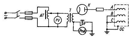
The scheme for testing the insulation of electrical equipment with increased alternating voltage is shown in fig. 1.
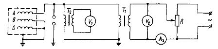
Rice. 1. Diagram of insulation test with increased AC voltage.
Before applying voltage to the test object, the fully assembled circuit is tested without load and the breakdown voltage of the ball stops is checked.
In addition to special, power transformers and voltage transformers can be used as test transformers.
Power transformers with this use allow a current load of up to 250% of the nominal with a triple (stepwise) test with a two-minute pause between voltage applications. For voltage transformers of the NOM type, it is permissible to increase the voltage of the primary winding to 150 - 170% of the nominal. In the absence of a test transformer with sufficient power, parallel connection of the same type of transformers is possible.
Voltage measurement transformers of the NOM type are widely used. Their maximum power, indicated in the passport data and due to the provision of an appropriate class of accuracy, is relatively small. However, according to heating conditions, they allow a short-term overload of 3 to 5 times the current value calculated from the maximum rated power. In addition, these transformers can be overexcited in voltage by 30-50%, you can connect two transformers in series.
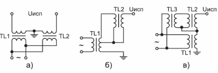
Rice. 2. Diagrams of series connection of test transformers: TL1 and TL2 — test transformers; TL3 is an isolation transformer.
The inclusion of two transformers according to the scheme of fig. 2a is applicable when both electrodes of the object can be isolated from earth. The test voltage is equal to the sum of the voltages of the two transformers; the nominal values of these voltages may vary. When the transformers are connected in cascade (Fig. 2a, b), one of them TL2 has a high potential and its body must be isolated from the ground.
This transformer can be excited using a special winding of the first transformer TL1 of the stage (Fig.2b) or directly from its secondary winding, if the maximum value of the voltage on it does not exceed the permissible value for the primary winding of the transformer TL2. If it is not possible to reliably isolate the transformer TL2, use the auxiliary isolation transformer TL3 (Figure 2c).
Power transformers are used to obtain phase or mains voltage. In the first case, the neutral of the HV winding is earthed and the primary voltage is applied to the neutral and the corresponding phase terminal of the LV winding.
It is assumed that the power of the transformer is equal to 1/3 of the nominal. Line-to-line voltage is used provided the neutral insulation is rated for full line-to-line voltage. In this case, one or two interconnected HV terminals are grounded. the power of the transformer is assumed equal to 2/3 of the nominal. Power transformers allow a short-term overcurrent of 2.5-3 times.
The regulating device should provide a change in the transformer voltage of 25-30% to the full value of the test voltage. The adjustment should be practically smooth, with steps not exceeding 1-1.5% of the test voltage. No circuit breaks are allowed during adjustment.
The voltage should be close to sinusoidal with a higher harmonic content of no more than 5%. When regulators with low internal resistance, such as autotransformers, are used, this requirement is practically met. It is not recommended to use chokes or rheostats for this purpose.
Rectified Voltage Insulation Test
Using a rectified test voltage can significantly reduce the power of the test setup, allows you to test large capacitance objects (capacitor cables, etc.) and allows you to monitor the condition of the insulation through measured leakage currents.
Half-wave rectifier circuits are commonly used in rectified voltage insulation testing. In fig. 3 shows a schematic diagram of a rectified voltage insulation test.
Rice. 3. Rectified voltage isolation test circuit
The rectified voltage insulation test method is similar to the AC voltage test. In addition, the leakage current is monitored.
The time of application of the corrected voltage is longer than in the AC voltage test and, depending on the equipment under test, is determined by the standards within 10 - 15 minutes.
The measurement of the test voltage is usually done with a voltmeter connected to the low voltage side of the test transformer (transformed by the transformation ratio).
 Since the rectified voltage is determined by the amplitude value, the voltmeter readings (measurement of effective voltage values) must be multiplied by internal resistance, rectifier lamp, small under normal cathode heating, increases sharply with insufficient heating current. In this case, the voltage drop in the rectifying lamp increases and decreases across the test object. Therefore, during testing, it is necessary to monitor the supply voltage of the test setup.It is also recommended to use a voltmeter with a large additional resistance to measure high side voltages.
As with AC voltage tests, to protect critical objects from accidental excessive voltage rise, it is recommended to connect a surge arrester with a breakdown voltage equal to 110-120% of the test voltage through a resistance (2 — 5 Ohm for each test voltage volts) in parallel with the test object.
The current passing through the insulation during a rectified voltage test in most cases does not exceed 5 — 10 mA, which leads to a small power of the test transformer.
When testing objects with a large capacity (power cables, capacitors, windings of large electrical machines), the capacitance of the object charged to the test voltage has a large energy reserve, the instantaneous discharge of which can lead to the destruction of the equipment of the test setup. Therefore, the test object must be discharged so that the discharge current does not pass through the measuring device.
To remove the charge from the tested objects, earthing devices are used, in the electrical circuit of which a resistance of 5-50 kOhm is included. Rubber tubes filled with water are used as resistance when dropping large capacity objects.
Charging the container, even after a short-term grounding, can continue for a long time and pose a danger to the lives of personnel. Therefore, after the test object has been discharged by the discharge device, it must be firmly grounded.