Preventive testing of cable lines
 Preventive testing of the insulation of cable lines is an organizational and technical measure that allows to identify defects in cables and connectors that occurred during the installation or operation of urban cable lines, in order to eliminate these defects in a timely manner and, therefore, prevent accidents and power shortages for consumers.
Preventive tests of cable lines of urban electric networks are carried out with increased DC voltages, the standardized values of which are given in the table. 1. The frequency of cable testing is given in a table. 2, and preventive measurements - in table. 3
Table 1. Values of DC test voltages when testing cables with a voltage of 3-10 kV
UNom cable line kV UInternet provider, kV Duration of test voltage application, min after laying during operation after laying during operation 3 18 15 10 5 6 36 30 10 60 50
Table 2. Frequency of preventive tests of cable lines of urban electric networks
Characteristics of the cable line Frequency of preventive tests Cable lines with a voltage of 3.6 and 10 kV operating in normal modes At least once in 1 year Cable lines laid in tunnels, collectors, substation buildings that are not subject to corrosion and mechanical damage and lack connectors, as well as end sleeves of obsolete structures installed outdoors At least once every 3 years Heavy cable lines and defective lines Installed by the chief engineer of the city electric network Cable lines of city electric networks laid in the ground and operated 5 or more years without electrical failure under operating conditions and preventive tests Installed by the chief engineer of the city electric network, taking into account local conditions, but at least once every 3 years
Table 3. Preventive measurements in cable lines
Type of measurement Controlled parameters Note Measurement of stray currents Potentials and currents on the cable sheaths in the test points Currents in the sections of the lines in the anode and variable zones are considered dangerous if the leakage currents to the ground are greater than 0.15 mA / dm2 Determination of chemical corrosion Corrosion activity of soils and natural waters The assessment is carried out when the cables are damaged by corrosion and there is no information about the corrosion conditions of the route. Measurement of current loads and voltages Current and voltage Measurements are made 2 times a year, including 1 time during the peak period Control of heating cables on sections of the track where there is a risk of overheating Temperature Measurements are made in accordance with local regulations. Testing of cables for voltage 3-6 kV with rubber insulation _ At least once a year
Phase-phase insulation of cable lines is tested according to a bipolar scheme (Fig. 1), in which the voltage between the conductors is twice the voltage of the conductors relative to the sheath (ground).
If it is necessary to detect insulation defects (insufficient insulation thickness, presence of cracks, breaks in paper strips, etc.) without breaking the tightness of the sheath, which cannot be detected during high voltage tests , the DC-AC test method is used in which the broken cable line (Fig.2) is tested for direct current with the simultaneous superposition of a small variable component fed by a separate transformer.
The power of the transformer is selected depending on the length and voltage of the tested cable line connected through the separation capacitor Cp, the capacity of which should approximately correspond to the capacity of the tested cable. For testing cable lines of urban electrical networks, a mobile testing installation and a torch are used, the schematic diagram of which is shown in fig. 3.
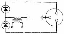
Rice. 1. Phase-to-phase insulation testing of a direct current cable line using a bipolar circuit
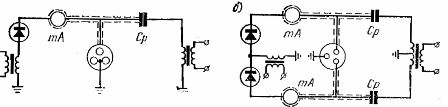
Rice. 2.Testing of the insulation of the direct alternating current cable line: a — according to the unipolar scheme; b — according to the bipolar scheme
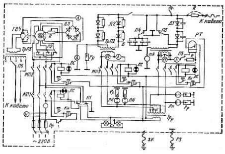
Rice. 3. Schematic diagram of a test rig mounted on a car
Pr — fuses; MP1 -MP4 — magnetic starters; P1 -P6 — switches; TrR — control transformer; ED — electric motor; TrP1 and TrP2 — step-up transformers; TrPZ-step-up high-frequency transformer; B — capacitor bank; GVCh — high-frequency generator; D1 — DZ — rectifiers; RT — relay; RR — restraints; LN — neon lamps; КН — buttons for turning on magnetic starters; LS — signal lamps; ST — signal board; RZ — working grounding; ZK — grounding of the machine body