Connection diagrams of thermoelectric pyrometers
 As the heat processes in furnaces are relatively slow, in most cases there is no need for continuous temperature measurement and one measuring device can be used to serve several thermocouple.
In the switching circuit of a pyrometric millivoltmeter for three thermocouples, the measuring device can be connected to each of three (or more) thermocouples by means of a switch. Multi-point (4, 6, 8, 12 and 20 points) readable rotary switches with reliable contacts are used for switching.
Both wires of the measuring device are always switched so that they do not have a common pole at the thermocouples, otherwise, especially in electric furnaces, leakages can occur between the thermocouples, which can damage both the device and the thermocouples themselves.
The readings of a pyrometric millivoltmeter are proportional to the current passing through its frame, and the latter obviously depends on the thermocouple developed by the thermocouple.to and from circuit resistance, i.e. millivoltmeter, thermocouple and connecting wires:
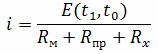
Since the resistances of the wires and thermocouples are not known in advance when calibrating the millivoltmeter, the device is calibrated with the so-called external resistor R included in the thermocouple circuit.VN made of manganin, with a resistance obviously greater than the possible total resistance (RNS+RT ).
However, even with very careful adjustment of the external resistance of the thermoelectric pyrometer circuit during assembly to its calibration value, it is not possible to completely eliminate the error introduced by the circuit resistance, since this resistance depends on temperature.
The thermoelectrodes themselves change their resistance depending on the temperature of the furnace, whether the wall of the furnace (through which they are inserted into the furnace) is cold or already heated. Compensation wires, depending on the ambient temperature, can also change their resistance, the same applies to the frame of the millivoltmeter.
The error from the change in the resistance of the pyrometer circuit due to heating is large enough and in most cases unacceptable.
A radical way to eliminate measurement errors associated with the presence and change of the resistance of the thermoelectric pyrometer circuit is the use of a compensation method for measuring thermoelectric power. To do this, use a DC potentiometer circuit in the compensation circuit (Fig. 1).
In this scheme, the thermoelectric the thermocouple Et is compared with the voltage drop across the section of the slide wire RR, in which a well-defined, set current is always maintained. Thus here, when measuring (switch P in position 2), the slide moves until the arrow of the zero device stop deflecting, and since, with a constant current in the record, the voltage drop across it is proportional to its length, the reocord can be calibrated directly in millivolts or directly in degrees.
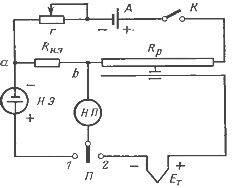
Rice. 1. Schematic diagram of a potentiometer with a constant current value in the compensation circuit.
A normal Weston element (NE) (or other stabilized voltage source) is used to check the current in the compensation circuit, e.g. etc. with. which is compared with the voltage drop in the reference resistance RTOI., for which the switch P becomes in position 1.
Since e. etc. s. of a normal element is strictly constant, then until the moment of equality e. etc. c. the voltage drop in Rn.e corresponds to a very specific current of the compensator circuit. The setting of this current is done using a rheostat r.In practice, such current standardization is required once a day as the battery (or battery) A voltage drops.
Since the sliding wire and the reference resistance can be performed with very high accuracy, as well as maintaining a constant current in the sliding wire using a normal element, the measurement accuracy in such potentiometers can be brought to 0.1%, and even technical devices have class 0 5.