How is the relay protection of power lines
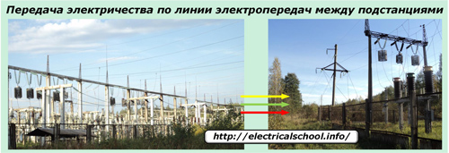
The continuous and reliable transport of electricity to consumers is one of the main tasks that are constantly solved by power engineers. To provide it, electrical networks consisting of distribution substations and connecting power lines were created. To move energy over long distances, supports are used to which connecting wires are suspended. They are insulated between themselves and the ground by a layer of ambient air. Such lines are called overhead lines by the type of insulation.
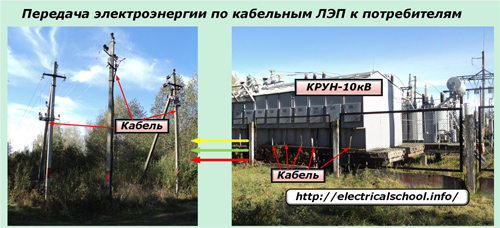
If the distance of the transport highway is short or for safety reasons it is necessary to hide the power line in the ground, then cables are used.
Overhead and cable power lines are constantly under voltage, the value of which is determined by the structure of the electrical network.
Purpose of the relay protection of power lines
In the event of insulation failure at any location on a cable or extended overhead line, the voltage applied to the line creates a leakage or short-circuit current through the damaged section.
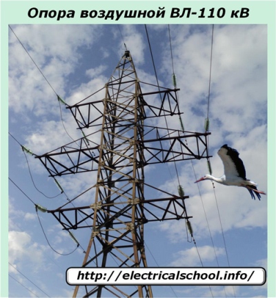
The reasons for breaking the insulation can be various factors that are able to eliminate or continue their destructive effect. For example, a stork flying between the wires of an overhead power line creates a phase-to-phase circuit with its wings and burns, falling nearby.
Or a tree growing very close to the support, during a storm, was knocked down on the wires by a gust of wind and caused them to short circuit.
In the first case, the short circuit occurred for a short period of time and disappeared, and in the second, the insulation violation was of a long-term nature and required removal by maintenance personnel.
Such damage can cause great damage to power plants. The currents of the resulting short circuits have a huge thermal energy, which can burn not only the wires of the power lines, but also destroy the power equipment of the power substations.
For these reasons, any damage to power lines that occurs must be repaired immediately. This is achieved by removing the voltage from the faulted line on the supply side. If such a power line receives power from both sides, then both must de-energize.
The functions of constant monitoring of the electrical parameters of the state of all power lines and removing the voltage from them from all sides in case of emergency situations are assigned to complex technical systems, which are traditionally called relay protection.
The adjective "relay" is derived from the elementary base based on electromagnetic relays, the designs of which arose with the appearance of the first power lines and are being improved to this day.
Modular protective devices, widely introduced in the practice of power engineers based on microprocessor technology and computer technology do not exclude a complete replacement of relay devices and, according to established tradition, are also introduced into relay protection devices.
Principles of relay protection
Network Monitoring Authorities
In order to monitor the electrical parameters of power lines, it is necessary to have instruments for their measurement, which are able to constantly monitor any deviations from the normal mode in the network and at the same time meet the conditions for safe operation.
In power lines with all voltages, this function is assigned to measuring transformers. They are classified into transformers:
-
current (TT);
-
voltage (VT).
Since the quality of the protective operation is of primary importance for the reliability of the entire electrical system, then increased requirements for the accuracy of operation are imposed on the measuring CTs and VTs, which are determined by their metrological characteristics.
Accuracy classes of measuring transformers for use in relay protection and automation devices (relay protection and automation) are standardized by the values «0.5», «0.2» and «P».
Instrument voltage transformers
A general view of the installation of voltage transformers on the 110 kV overhead line is shown in the photo below.
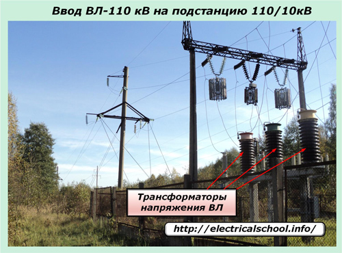
Here it can be seen that VTs are not installed anywhere along an extension line, but on the switchgear of an electrical substation. Each transformer is connected by its primary terminals to the corresponding conductor of the overhead line and ground circuit.
The voltage converted from the secondary windings is output through the switches 1P and 2P through the corresponding conductors of the power cable. For use in protective and measuring devices, the secondary windings are connected according to the "star" and "delta" scheme, as shown in the photo for VT-110 kV.
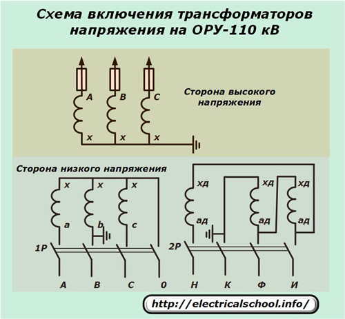
To decrease voltage loss and precise operation of the relay protection, a special power cable is used and increased requirements are imposed on its installation and operation.
Measuring VTs are created for each type of line voltage and can be switched according to different schemes to perform specific tasks. But they all work on the general principle of converting the linear value of the transmission line voltage into a secondary value of 100 volts, accurately copying and emphasizing all the characteristics of the primary harmonics at a certain scale.
The transformation ratio of VT is determined by the ratio of the line voltages of the primary and secondary circuits. For example, for the considered 110 kV overhead line, it is written as follows: 110000/100.
Instrument current transformers
These devices also convert the primary line load to secondary values with maximum repetition of any changes in the harmonics of the primary current.
For easier operation and maintenance of electrical equipment, they are also installed on distribution devices of substations.

Current transformers They are included in the overhead line circuit in a different way than VT: they with their primary winding, which is usually represented by only one turn in the form of a direct current wire, are simply cut into each wire of the line phase.This can be clearly seen in the above photo.
The CT transformation ratio is determined by the ratio of the selection of nominal values at the stage of the design of the power line. For example, if the power line is designed to carry 600 amps and 5 A will be removed from the CT secondary, then the designation 600/5 is used.
In electricity, two standards are accepted for the values of the secondary currents that are used:
-
5 A for all CTs up to and including 110 kV;
-
1 A for lines 330 kV and higher.
Secondary TT windings are connected for connection to protective devices according to different schemes:
-
full star;
-
incomplete star;
-
triangle.
Each compound has its own specific characteristics and is used for certain types of protection in different ways. An example of connecting current transformers and current relay coils to a full star circuit is shown in the photo.

This is the simplest and most common harmonic filter used in many protective relay circuits. In it, the currents from each phase are controlled by a separate relay of the same name, and the sum of all vectors passes through the coil included in the common neutral wire.
The method of using current and voltage measuring transformers makes it possible to transfer the primary processes taking place on the power equipment to the secondary circuit on an accurate scale for their use in the relay protection hardware and the creation of algorithms for the operation of the logic devices to eliminate emergency equipment processes.
Authorities for processing the received information
In relay protection, the main working element is a relay — an electrical device that performs two main functions:
-
monitors the quality of the observed parameter, for example, current, and in normal mode it stably maintains and does not change the state of its contact system;
-
when a critical value called a set point or response threshold is reached, it immediately switches the position of its contacts and remains in this state until the observed value returns to the normal range.
The principles of forming circuits for switching current and voltage relays in secondary circuits help to understand the representation of sinusoidal harmonics by vector quantities with their representation in a complex plane.
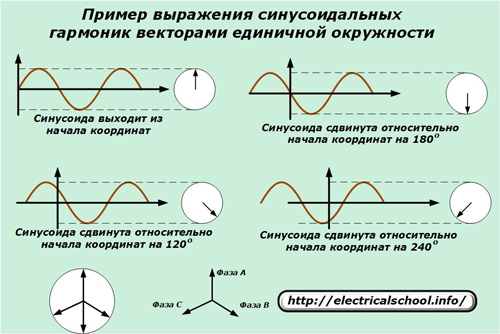
In the lower part of the picture, a vector diagram is shown for a typical case of distribution of sinusoids in three phases A, B, C in the mode of operation of consumer power supply.
Monitoring the condition of current and voltage circuits
In part, the principle of processing secondary signals is shown in the circuit for turning on the CT and relay windings according to the full star and VT scheme of the ORU-110. This method allows you to add vectors in the following ways.

The inclusion of the relay coil in any of the harmonics of these phases allows you to fully control the processes taking place in it and turn off the circuit from operation in case of accidents. To do this, it is enough to use suitable designs of relay devices for current or voltage.
The above schemes are a special case of the versatile use of different filters.
Methods of controlling the power passing through the line
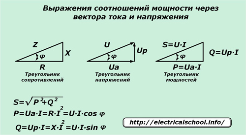
Relay protection devices control the power value based on the readings of all the same current and voltage transformers.In this case, well-known formulas and ratios of total, active and reactive power between them and their values expressed by the vectors of currents and voltages are used.
It is understood that the current vector is formed by the applied emf to the line resistance and overcomes its active and reactive parts equally. But at the same time, in the sections with components Ua and Up, a voltage drop occurs according to the laws described by the voltage triangle.
Power can be transferred from one end of the line to the other and even reversed when transporting electricity.
Changes in its direction are the result of:
-
switching loads by operating personnel;
-
power fluctuations in the system due to the effects of transients and other factors;
-
emergence of emergency modes.
Power relays (PMs) operating as part of the relay protection and automation system take into account fluctuations in its directions and are configured to operate when the critical value is reached.
Line resistance control methods
Relay protection devices that calculate the distance to the short circuit location based on electrical resistance measurements are called distance or DZ protection for short. They also use current and voltage transformer circuits in their work.
To measure the resistance, use An expression of Ohm's lawdescribed for the circuit section under consideration.
When a sinusoidal current passes through active, capacitive and inductive resistance, the voltage drop vector on them deviates in different directions. This is taken into account by the behavior of the protective relay.
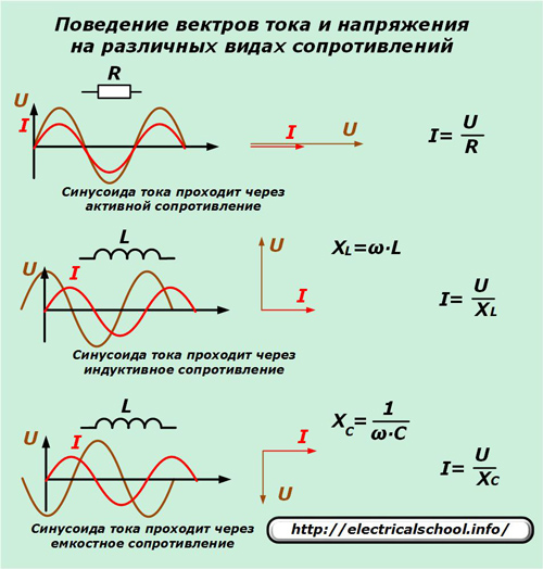
According to this principle, many types of resistor relays (RS) work in relay protection and automation devices.
Line frequency control methods
To maintain the stability of the oscillation period of the harmonics of the current transmitted through the power line, frequency control relays are used. They work on the principle of comparing the reference sine wave produced by the built-in generator with the frequency obtained by the linear measuring transformers.
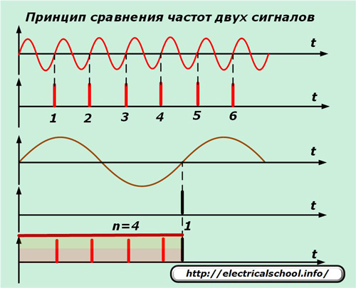
After processing these two signals, the frequency relay determines the quality of the observed harmonic and, when the set value is reached, changes the position of the contact system.
Features of line parameter control by digital protections
Microprocessor developments that replace relay technologies also cannot work without secondary values of currents and voltages, which are removed from the measuring transformers TT and VT.
For the operation of digital protections, information about the secondary sine wave is processed by sampling methods, which consist in superimposing a high frequency on an analog signal and fixing the amplitude of the controlled parameter at the intersection of the graphs.

Due to the small sampling step, fast processing methods and use of the mathematical approximation method, high accuracy of measurement of secondary currents and voltages is obtained.
The numerical values calculated in this way are used in the algorithm for the operation of microprocessor devices.
The logical part of relay protection and automation
After the initial values of the currents and voltages of the electricity transmitted along the power line are modeled by measuring transformers selected for processing by filters and received by the sensitive organs of the relay devices for current, voltage, power, resistance and frequency, it is the turn of the circuits of the logic relays.
Their design is based on relays operating from an additional source of constant, rectified or alternating voltage, which is also called operational, and the circuits fed by it are operational. This term has a technical meaning: very quickly, without unnecessary delays, to perform their switches.
The speed of operation of the logic circuit largely determines the speed of emergency shutdown and therefore the degree of its destructive consequences.
In the way they perform their tasks, relays working in operating circuits are called intermediate: they receive a signal from the measuring protective device and transmit it by switching their contacts to executive bodies: output relays, solenoids, electromagnets for disconnection or closing the power switches.
Intermediate relays usually have several pairs of contacts that work to make or break a circuit. They are used to simultaneously reproduce commands between different relay protection devices.
In the operation algorithm of the relay protection, a delay is often introduced to ensure the principle of selectivity and to form the sequence of a certain algorithm. It blocks the protection operation during setup.
This delay input is created using special time relays (RVs) that have a clock mechanism that affects the speed of their contacts.
The logic part of the relay protection uses one of many algorithms designed for different cases that can occur on a power line of a certain configuration and voltage.
As an example, we can give only some names of the operation of the logic of two relay protections based on the control of the current of the power line:
-
current interruption (speed indication) without delay or with delay (guarantees RF selectivity), taking into account the direction of power (due to the RM relay) or without it;
-
overcurrent protection can be provided with the same controls as the disconnect, complete with or without line low voltage checks.
Elements of automation of various devices are often introduced into the operation of the relay protection logic, for example:
-
single-phase or three-phase power switch reclosing;
-
turning on the backup power supply;
-
acceleration;
-
frequency unloading.
The logic part of the line protection can be done in a small relay compartment directly above the power switch, which is typical for external complete switchgear (KRUN) with voltage up to 10 kV, or occupy several 2x0.8 m panels in the relay room .
For example, the protection logic for a 330 kV line can be placed on separate protection panels:
-
reserve;
-
DZ — remote;
-
DFZ — differential phase;
-
VCHB — high frequency blocking;
-
OAPV;
-
acceleration.
Output circuits
The output circuits serve as the final element of the linear relay protection. Their logic is also based on the use of intermediate relays.
The output circuits form the order of operation of the line breakers and determine the interaction with adjacent connections, devices (for example, breaker failure protection — emergency tripping of the breaker) and other elements of relay protection and automation.
Simple line protections may have only one output relay that trips the breaker. In complex systems with branched protection, special logic circuits are created that work according to a certain algorithm.
The final removal of voltage from the line in the event of an emergency is carried out by means of a power switch, which is activated by the force of the tripping electromagnet. Special power chains are supplied for its operation, which can withstand powerful loads.Ki.