Transformer short circuit mode
 The short-circuit mode of the transformer is such a mode when the terminals of the secondary winding are closed by a current conductor with a resistance equal to zero (ZH = 0). A short-circuit of the transformer during operation creates an emergency mode, since the secondary current, and therefore the primary current, increases several tens of times compared to the nominal one. Therefore, in circuits with transformers, protection is provided that automatically switches off the transformer in the event of a short circuit.
In laboratory conditions, it is possible to carry out a test short circuit of the transformer, in which the terminals of the secondary winding are short-circuited, and a voltage Uk is applied to the primary, in which the current in the primary winding does not exceed the nominal value (Ik < I1nom). In this case, the voltage Uk, expressed in percent, with Ik = I1nom, is denoted by uK and is called the short-circuit voltage of the transformer. it characteristic of the transformerindicated in the passport.
Thus (%):

where U1nom is the rated primary voltage.
The short circuit voltage depends on the higher voltage of the transformer windings. For example, at a higher voltage of 6-10 kV uK = 5.5%, at 35 kV uK = 6.5 ÷ 7.5%, at 110 kV uK = 10.5%, etc. As you can see, as the rated voltage increases, the short circuit voltage of the transformer increases.
When the voltage Uc is 5-10% of the rated primary voltage, the magnetizing current (no-load current) decreases 10-20 times or even more significantly. Therefore, in short-circuit mode it is considered that

The main magnetic flux F also decreases by a factor of 10–20, and the leakage currents of the windings become commensurate with the main flux.
Since when the secondary winding of the transformer is short-circuited, the voltage at its terminals is U2 = 0, e. etc. pp. because it takes the form
and the voltage equation for the transformer is written as
This equation corresponds to the transformer equivalent circuit shown in Fig. 1.
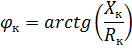
The vector diagram of the short-circuit transformer corresponding to the equation and the diagram in Fig. 1 is shown in FIG. 2. Short-circuit voltage has active and reactive components. The angle φk between the vectors of these voltages and currents depends on the ratio between the active and reactive inductive components of the transformer resistance.
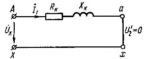
Rice. 1. Equivalent circuit of the transformer in case of short circuit
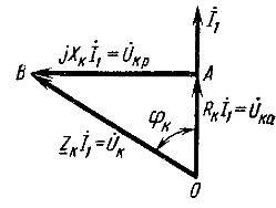
Rice. 2. Vector diagram of the transformer under short circuit
For transformers with rated power 5-50 kVA XK / RK = 1 ÷ 2; with rated power 6300 kVA or more XK / RK = 10 or more. Therefore, it is believed that for high power transformers UK = Ucr and the impedance ZK = Xk.
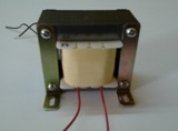
Short circuit experience.
This experiment, like the no-load experiment, is conducted to determine the parameters of the transformer. A circuit is assembled (Fig. 3) in which the secondary winding is short-circuited by a metal jumper or wire with a resistance close to zero. A voltage Uk is applied to the primary winding, at which the current in it is equal to the nominal value I1nom.
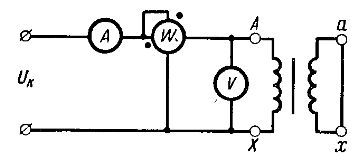
Rice. 3. Schematic of the transformer short-circuit experiment
According to the measurement data, the following parameters of the transformer are determined.
Short circuit voltage
where UK is the voltage measured with a voltmeter at I1, = I1nom. In short-circuit mode, UK is very small, so no-load losses are hundreds of times smaller than at nominal voltage. Thus, we can assume that Ppo = 0 and the power measured by the wattmeter is the power loss Ppk, due to the active resistance of the transformer windings.
 At current I1, = I1nom get nominal power losses for heating the windings Rpk.nom, which are called electrical losses or short-circuit losses.
From the voltage equation for the transformer, as well as from the equivalent circuit (see Fig. 1), we obtain


where ZK is the impedance of the transformer.
By measuring Uk and I1 you can calculate transformer impedance

The power loss during a short circuit can be expressed by the formula

Hence active resistance of the transformer windings

found from the wattmeter and ammeter readings. Knowing Zk and RK, you can calculate the inductive resistance of the windings:
Knowing the Zk, RK and Xk of the transformer, you can build the short-circuit voltages of the main delta (triangle OAB in Fig. 2), and also determine the active and inductive components of the short-circuit voltage: