Electromagnetic grinding plates
 Electromagnetic plates are widely used in surface grinding machines. The steel parts to be machined placed on these plates are held in place during machining by the magnetic attraction of the plate. Electromagnetic clamping has advantages over jaw clamping. Including the current, you can immediately fix many parts located on the surface of the plate.
With electromagnetic clamping, greater processing accuracy can be achieved because the workpiece is not compressed laterally when heated during processing and can expand freely. With electromagnetic clamping, it is possible to machine parts from the end and from the side.
However, electromagnetic clamping does not provide as high forces as clamping using cams. In the event of an emergency interruption of the power supply to the coil of the electromagnetic plate, the part is torn off from its surface. Therefore, electromagnetic plates are not used for high cutting forces. In addition, steel parts machined on electromagnetic plates often retain residual magnetism.
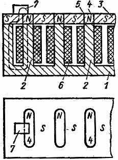
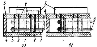
The electromagnetic plate (Fig. 1) has a body 1 made of mild steel, the bottom of which is provided with protrusions of poles 2. A cover 3 is placed on top, in which sections 4 located above the poles are separated by intermediate layers 5 of non-magnetic material (lead and antimony alloy, tin alloys, bronze, etc.).
When a direct current flows through the coils 6, all sections of the outer surface of the cover (mirror), surrounded by non-magnetic intermediate layers, are one pole (for example, the north); the rest of the surface of the plate — with the other pole (for example, the southern one). The processed part 7, which overlaps the non-magnetic intermediate layer everywhere, closes the magnetic flux of one of the poles 2 and is therefore attracted to the surface of the plate.
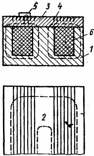
For fixing small details, it is desirable that the distance between the poles 2 be as small as possible. However, this is difficult to implement, since the turns of two coils 6 must be placed between the poles. Therefore, electromagnetic plates with channels filled with non-magnetic material are used to fix small parts (Fig. 2).
This plate has only one coil 2. The body 1 of the plate is covered with a thick steel cover 3 with closely spaced non-magnetic grooves 4. When a small workpiece 5 is placed on the blank 5, part of the magnetic flux of the coil will be closed through the cover 3 under the grooves , and part of it, bending around the non-magnetic groove covered by part 5, will pass through the workpiece, ensuring its attraction. Since only part of the magnetic flux passes through the part, the attraction force of these plates is lower than that of plates with through layers.
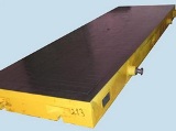
In addition to electromagnetic plates designed for reciprocating movement, rotating electromagnetic plates, commonly called electromagnetic tables, are widely used.
Rice. 1. Electromagnetic cooker
Rice. 2. Electromagnetic plate for small parts
Rice. 3. Table with fixed electromagnets
Rice. 4. Switch on the electromagnetic cooker
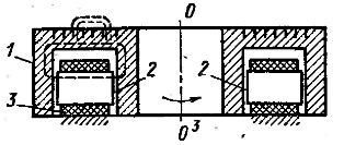
Tables with fixed electromagnets are also used in industry (Fig. 3). The body 1 of the table rotates over the stationary electromagnets 2 located around the circumference. When a direct current flows through the coil 3, the magnetic flux closes (as shown in Fig. 3 with a dotted line), ensuring the attraction of the part.
Electromagnetic tables of this type, in addition to the non-magnetic channels located along the concentric circles, have through radial non-magnetic intermediate layers that divide the body of the table and its working surface into sectors that do not have a magnetic connection with each other. If the electromagnets 2 are not located around the entire circumference, then a sector is formed on such a table, on which the parts will not be fixed and can be easily removed. The table with stationary electromagnets rests on ring-shaped guides made of non-magnetic material (usually bronze). This eliminates the possibility of closing the flux under the electromagnets.
The attraction force of the electromagnetic plate depends largely on the material and size of the fixed part, the number of parts on its surface, the position of the part on the plate and the design of the plate: the attraction force of electromagnetic plates varies between 20-130 N / cm2 (2-13 kgf / cm2).
During operation, the electromagnetic cooker heats up, during shutdown it cools down. This causes air to move through any leaks, as a result of which moisture can condense inside the countertop. Therefore, in the design of electromagnetic cookers, it is important to ensure the protection of the coils of the cooker from the effects of the cooling liquid. For this, the inner cavity of the plate is poured with bitumen.
To power electromagnetic cookers, direct current with a voltage of 24, 48, 110 and 220 V is used. Most often, a current with a voltage of 110 V is used. Powering electromagnetic cookers with alternating current is unacceptable due to the strong demagnetizing and heating effect of eddies currents.
The coils of the individual poles of an electromagnetic plate are usually connected in series. Less often they are used for switching from series to parallel, using 110 V with parallel connection of coils and 220 V with series. The power consumed by electromagnetic cookers is 100-300 watts. Selenium rectifiers are commonly used as a power source for electromagnetic cookers. The rectifier kit includes a transformer, fuse and switch.
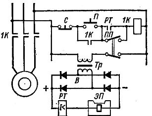
The scheme for turning on the electromagnetic plate is shown in fig. 4. If the PP switch is in the position indicated in the diagram, the table drive (and circle rotation if necessary) can only be started when the electromagnetic plate is turned on. In this case, the coil of the electromagnetic plate EP receives power from the rectifier B connected to the grid through the transformer Tr.
The coil of the current relay RT is connected in series with this coil, the closing contact of which is connected in series with the coil of the 1K contactor. If, as a result of some accident, the power supply to the electromagnetic plate is interrupted, the current relay RT with its contact will break the circuit of the coil 1K and the rotary motor of the table (often of the grinding wheel) is turned off. Turning the PP switch allows the motor to be turned on without a nameplate.
In this case, the possibility of breaking the insulation of the coil of the electromagnetic plate when it is turned off is excluded. The winding circuit after the plate is turned off remains closed through the arms of the rectifier.
Due to the presence of residual magnetism, steel parts after processing are often difficult to remove from the plate. To facilitate the removal of parts, a small current flows in the opposite direction through the coil of the electromagnetic plate after the end of processing. A special flexible wire in a rubber sheath is usually used to supply current to the plate with a short stroke length.
With the translational movement of the plate over a greater distance, copper tires are used with brushes sliding on them. Heavy machines use trolley wires. Current is supplied to the electromagnetic masses through slip rings.
In addition to the considered electromagnetic fasteners, plates are used with permanent magnets… These cookers do not require power sources and therefore there can be no sudden detachment of parts from the surface of the cooker during a power failure. In addition, permanent magnet plates are more reliable in operation.
Rice. 5.Permanent magnet cooker
Rice. 6. Magnetic device
Rice. 7. Degreaser
The plate (Fig. 5, a) has a housing 4, inside which is a package of permanent magnets 2. Between the magnets are placed soft iron rods 1, separated from the magnets by spacers 6 of non-magnetic material. The package is fastened with brass bolts 8. It rests on a base 3, made of mild steel, and on top is covered with a plate 5, also made of mild steel. Plate 5 has non-magnetic interlayers separating portions of its surface located above the poles. The body 4 of the plate is made of silimine or non-magnetic cast iron. The steel blank 7 placed on the plate 5 is attracted by the poles below it. The magnetic fluxes of the poles are closed, as shown by the dashed line in Fig. 5, a.
To remove the part from the electromagnetic plate, the pole pack is moved. In this position of the poles, their magnetic fluxes are closed, bypassing part 7 (dotted line in Fig. 5, b). In this case, the part can be easily removed. The bag is moved manually using an eccentric not shown in the figure.
The internal cavity of the plate is filled with a viscous anti-corrosion grease that reduces the force required to move the magnet block. Stationary, rotating, sine, marking, scraping and other plates with permanent magnets are used in industry.
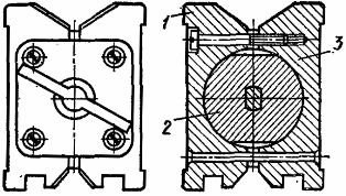
The magnetic device for cross-drilling rolls is shown in fig. 6. If the permanent magnet 2 is in the position shown in fig. 6, the part is fixed and the fixture is drawn to the steel table of the machine.When the magnet 2 is rotated 90 °, the magnetic flux is closed through the steel parts 1 and 3 of the device body, and the attraction of the part and the device stops.
Rice. 8 Grinding machine with electromagnetic plate
Permanent magnet devices are also used as the basis of an indicator stand, lamp, coolant fitting, rectifier, etc. After disassembly, permanent magnet devices require magnetization in a special installation.
Plates with such magnets are characterized by a high attraction force. Ferrite ceramic permanent magnets are used in milling, planing and other machines.
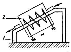
To eliminate the residual magnetism of the processed parts, special demagnetizers are used. The demagnetizer shown in fig. 7 is intended for demagnetization of mass-produced parts (rings with ball bearings). The parts slide on an inclined bridge 1 made of non-magnetic material. At the same time, they pass inside the coil 2, which is supplied with an alternating current, and, subject to the reversal of magnetization by an alternating field, lose residual magnetism. The field strength weakens as the moving part moves away from the coil 2. These devices are installed directly on the machines.