Comparative method with measure
 In measuring technology, a method is often used to improve accuracy, which is based on comparing the value of the measured quantity with the value of the quantity reproduced by a special measure. In this case, the different (differential) signal is measured, and since the measurement usually has a small error, high measurement accuracy is ensured.
This method is the basis of the operation of measuring bridges and potentiometers.
Usually, the value reproduced by the measure is adjusted, and in the process of measurement, its value is set exactly equal to the value of the measured value.
When measuring bridges, resistances are used as such a measure - rheochords, with the help of which the resistance of the thermal transducer is balanced, which changes when the temperature of the object changes.
A stable voltage source with a regulated output is usually used in measuring potentiometers. In the course of measurements, using the voltage of such a source, the EMF generated by the sensor is compensated. In this case, this measurement method is called compensation.
In both cases, the task of the following devices (devices) is only to register the fact of equality of the measured value and the measure, therefore the requirements for them are significantly reduced.
Determination of temperature by measuring bridges
As an example, consider the principle of operation of the measuring bridge in manual mode.
Figure 1a shows a bridge circuit for measuring the temperature Θ of a certain object to control OR (or measure OI). The basis of such a circuit is a closed circuit of four resistors RTC, Rp, Rl, R2, forming the so-called bridge arms. The connection points of these resistors are called vertices (a, b, c, d), and the lines connecting opposite vertices (a-b, c-d) are called diagonals of the bridge. One of the diagonals (c-d, Fig. 1.a) is supplied with supply voltage, the other (a-b) is measuring or output. Such a circuit is called a bridge, which gives the name to the entire measuring device.
The RTC resistor is a primary temperature measurement transducer (thermistor) located in close proximity to the measurement object (often inside it) and connected to the measurement circuit using wires up to several meters long.
The main requirement for such a thermal converter is the linear dependence of its active resistance RTC on the temperature in the required measurement range:

where R0 is the nominal resistance of the thermal converter at temperature Θ0 (usually Θ0 = 20 ° C):
α — temperature coefficient depending on the material of the thermal converter.
The most commonly used metal thermistors TCM (copper) and TSP (platinum), are sometimes called metal thermistors (MTP).
The variable resistor Rp is the high-precision rheochord (measurement) discussed above and serves to balance the variable RTC. Resistors R1 and R2 complete the bridge circuit. In case of equality of their resistances R1 = R2, the bridge circuit is called symmetrical.
In addition, FIG. 1.a shows a null device (NP) for fixing the balance of the bridge and an arrow with a scale graduated in degrees Celsius.
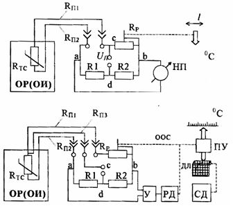
Rice. 1. Temperature measurement by measuring bridges: a) in manual mode; b) in automatic mode
It is known from electrical engineering that the condition for balance (equilibrium) of the bridge is realized when the product of the resistances of the opposite arms of the bridge is equal, i.e. taking into account the resistance of the wires that connect the sensor:

where Rp = Rp1 + Rp2 is the sum of the wire resistances; or for symmetrical bridge (R1 = R2)

In this case, there is no voltage in the measuring diagonal and the zero device indicates zero.
When the temperature Θ of the object changes, the resistance of the RTC sensor changes, the balance is disturbed, and it must be restored by moving the slider of the sliding wire.
In this case, together with the slider, the arrow will move along the scale (the dotted lines in Fig. 1.a denote the mechanical connection between the slider and the arrow).
Readings are made only at moments of equilibrium, which is why such circuits and devices are often called balanced measuring bridges.
The main disadvantage of the measuring circuit shown in fig. 1.a, is the presence of an error caused by the resistance of the wires Rp, which can vary depending on the ambient temperature.
This error can be eliminated by using a three-wire method of connecting the sensor (see Figure 1.b).
Its essence lies in the fact that with the help of the third wire, the upper «c» of the supply diagonal is moved directly to the thermal resistance, and the two remaining wires Rп1 and Rп2 are in different adjacent arms, i.e. the balance state of a symmetrical bridge is transformed as follows:

Thus, to completely eliminate the error, it is enough to use the same wires (Rp1 = Rp2) when connecting the sensor to the bridge circuit.
Automatic temperature control system
To implement the automatic measurement mode (Fig. 1b), it is enough to connect a phase-sensitive amplifier (U) and a reversible motor (RD) with a gearbox to the measuring diagonal instead of a zero device.
Depending on the nature of the object's temperature change, the taxiway will move the RP slider in one direction or the other until balance is established. The voltage across the a-b diagonal will disappear and the motor will stop.
In addition, the engine will move the indicator pointer and the recorder (PU) if necessary to record the readings on the chart strip (DL). The graphics bar is driven at a constant speed by a synchronous motor (SM).
From the point of view of automatic control theory, this measuring installation is a system of automatic control (SAK) temperature and belongs to the class of servo systems with negative feedback.
The feedback function is accomplished by mechanically connecting the motor shaft RD to the record Rp. The set point is the TC thermocouple. In this case, the bridge circuit performs two functions:
1. comparing device

2.converter (ΔR to ΔU).
The voltage ΔU is an error signal
The reversing motor is an executive element, and the output value is the movement of 1 arrow (or recording unit), since the purpose of each SAC is to provide information about the controlled value in a form convenient for human perception.
The actual circuit of the KSM4 measuring bridge (Fig. 2) is slightly more complicated than that shown in Fig. 1.b.
Resistor R1 is a rechord — a wire of high electrical resistance wound on an insulated wire. The movable motor slides on the slide wire and across a copper bus parallel to the slide wire.
In order to reduce the influence of the transient contact resistance of the motor on the accuracy of the measurement, two parts of the sliding wire, separated from the motor, are included in different arms of the bridge.
The purpose of the remaining resistors:
• R2, R5, R6 — maneuver, to change the measurement limits or scale range,
• R3, R4 — to set (select) the temperature at the beginning of the scale,
• R7, R9, P10 — complete the bridge circuit;
• R15 — to adjust the equality of the resistances of the wires Rп on different arms of the bridge,
• R8 — to limit the thermistor current;
• R60 — to limit the input current of the amplifier.
All resistors are made of manganin wire.
The bridge is powered by alternating voltage (6.3 V) from a special winding of the mains transformer.
Amplifier (U) — phase-sensitive AC.
The executive reversible motor (RD) is a two-phase induction motor with a built-in gearbox.
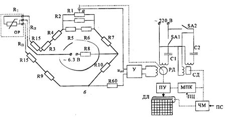
Rice. 2. Schematic of the KSM4 device in single-channel temperature measurement mode.