Electric drive devices
 Different actuators are used to close and open the contacts of electrical devices. In a manual drive, power is transmitted from the human hand through a system of mechanical transmissions to the contacts. Manual actuation is used in some disconnectors, circuit breakers, circuit breakers and controllers.
Most often, manual actuation is used in non-automatic devices, although in some protective devices, switching on is done manually and switching off automatically under the action of a compressed spring. Remote drives include electromagnetic, electropneumatic, electric motor and thermal drives.
Electromagnetic drive
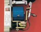
The most widely used in electrical devices is an electromagnetic drive that uses the force of attraction of the armature to the core electromagnet or the pulling force of the anchor solenoid coil.
Any ferromagnetic material placed in a magnetic field acquires the properties of a magnet. Therefore, a magnet or electromagnet will attract ferromagnetic bodies to itself.This property is based on the devices of various types of lifting, retracting and rotating electromagnets.
A force F with which the electromagnet or permanent magnet attracts a ferromagnetic body — an anchor (Fig. 1, a),
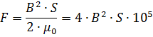
where B is the magnetic induction in the air gap; S is the cross-sectional area of the poles.
The magnetic flux F created by the coil of the electromagnet and therefore the magnetic induction B in the air gap, as mentioned above, depend on the magnetomotive force of the coil, i.e. of the number of turns w and the current Flows through it. Therefore, the force F (pulling force of the electromagnet) can be adjusted by changing the current in its coil.
The properties of the electromagnetic drive are characterized by the dependence of the force F on the position of the armature. This dependence is called the traction characteristic of the electromagnetic drive. The shape of the magnetic system has a significant influence on the course of the traction characteristic.
A magnetic system consisting of a U-shaped core 1 (Fig. 1, b) with a coil 2 and a rotating armature 4, which is connected to the movable contact 3 of the apparatus, has become widespread in electrical devices.
An approximate view of the traction characteristics is shown in fig. 2. When the contacts are fully open, the air gap x between the armature and the core is relatively large and the magnetic resistance of the system will be the largest. Therefore, the magnetic flux F in the air gap of the electromagnet, the induction B and the pulling force F will be the smallest. However, with a correctly calculated drive, this force should ensure the attraction of the anchor to the core.
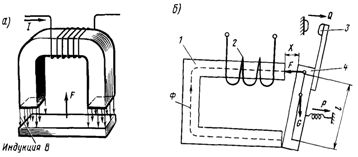
Rice. 1.Schematic diagram of an electromagnet (a) and diagram of an electromagnetic drive with a U-shaped magnetic circuit (b)
As the armature moves closer to the core and the air gap decreases, the magnetic flux in the gap increases and the pulling force increases accordingly.
The thrust force F created by the drive must be sufficient to overcome the drag forces of the vehicle's propulsion system. These include the force of the weight of the moving system G, the contact pressure Q and the force P created by the return spring (see Fig. 1, b). The change in the resulting force when moving the anchor is shown in the diagram (see Fig. 2) by the dashed line 1-2-3-4.
As the armature moves and the air gap x decreases until the contacts touch, the drive only has to overcome the resistance due to the mass of the moving system and the action of the return spring (section 1-2). In addition, the effort increases sharply with the value of the initial pressing of the contacts (2-3) and increases with their movement (3-4).
A comparison of the characteristics shown in Fig. 2, allows us to judge the operation of the apparatus. So if the current in the control coil produces ppm.I2w to, then the largest gap x at which the device can turn on is x2 (point A) and at lower ppm. I1w, the pulling force will not be sufficient and the device can only turn on when the gap decreases to x1 (point B).
When the electrical circuit of the drive coil opens, the moving system returns to its original position under the action of spring and gravity.At small values of the air gap and restoring forces, the armature can be held in an intermediate position by the residual magnetic flux. This phenomenon is eliminated by setting a fixed minimum air gap and adjusting the springs.
Circuit breakers use systems with a holding electromagnet (Fig. 3, a). The armature 1 is held in an attracted position to the yoke of the core 5 by the magnetic flux F generated by the holding coil 4 which is fed by the control circuit. If it is necessary to disconnect, a current is supplied to the disconnecting coil 3, which creates a magnetic flux Fo directed to the magnetic flux Fu of the coil 4, which demagnetizes the armature and core.
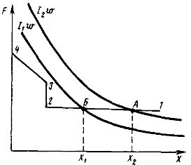
Rice. 2. Traction characteristics of electromagnetic drive and force diagram
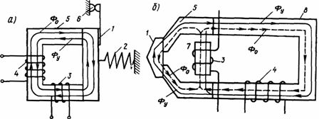
Rice. 3. Electromagnetic drive with holding electromagnet (a) and with magnetic shunt (b)
As a result, the armature under the action of the disconnecting spring 2 moves away from the core and the contacts 6 of the device open. The tripping speed is achieved due to the fact that at the beginning of the movement of the movable system, the greatest forces of the tensioned spring act, while in the conventional electromagnetic drive, discussed earlier, the movement of the armature begins with a large gap and a low traction effort.
As the actuating coil 3 in circuit breakers, busbars or demagnetizing coils are sometimes used, through which the current of the supply circuit protected by the device passes.
When the current in coil 3 reaches a certain value determined by the setting of the apparatus, the resulting magnetic flux Fu — Fo passing through the armature decreases to such a value that it can no longer hold the armature in a pulled state, and the apparatus is turned off.
In high-speed circuit breakers (Fig. 3, b), the control and closing coils are installed in different parts of the magnetic circuit to avoid their mutual inductive influence, which slows down the demagnetization of the core and increases its own tripping time, especially at high rates of increase in emergency current in the protected circuit.
The tripping coil 3 is mounted on the core 7, which is separated from the main magnetic circuit by air gaps.
The armature 1, cores 5 and 7 are made in the form of packages of steel sheet, and therefore the change of the magnetic flux in them will exactly correspond to the change of the current in the protected circuit. The flux Fo created by the cut-off coil 3 is closed in two ways: through the armature 1 and through the uncharged magnetic circuit 8 with the control coil 4.
The distribution of the flux Ф0 along the magnetic circuits depends on the rate of its change. At high rates of increase of the emergency current, which in this case creates a demagnetizing flux Ф0, all this flux begins to flow through the armature, since a rapid change in the part of the flux Fo passing through the core with the coil 4 of the emf is prevented. d. s induced in the holding coil when the current through it changes rapidly. This e. etc. c. according to Lenz's rule, it creates a current that slows down the growth of that part of the flow Fo.
As a result, the tripping speed of the high-speed circuit breaker will depend on the rate of increase of the current passing through the closing coil 3. The faster the current increases, the lower the current, the tripping of the apparatus begins. This property of a high-speed circuit breaker is very valuable because the current has the highest speed in the short-circuit modes and the sooner the circuit breaker begins to break the circuit, the smaller the current limited by it will be.
In some cases, it is necessary to slow down the operation of the electrical apparatus. This is done with the help of a device for obtaining a time delay, which is understood as the time from the moment the voltage is applied or removed from the drive coil of the apparatus to the start of the movement of the contacts. The delay for turning off electrical devices controlled by direct current, is carried out by means of an additional short-circuit coil located on the same magnetic circuit with the control coil.
When power is removed from the control coil, the magnetic flux created by this coil changes from its operating value to zero.
When this flux changes, a current is induced in the short-circuited coil in such a direction that its magnetic flux prevents the reduction of the magnetic flux of the control coil and holds the armature of the electromagnetic drive of the apparatus in the attracted position.
Instead of a short circuit coil, a copper sleeve can be installed on the magnetic circuit. Its action is similar to that of a short circuit coil. The same effect can be achieved by short-circuiting the circuit of the control coil at the moment when it is disconnected from the network.
To obtain the shutter speed for turning on the electrical apparatus, various mechanical timing mechanisms are used, the principle of operation of which is similar to a clock.
Electromagnetic device drives are characterized by current (or voltage) actuation and return. Operating current (voltage) is the smallest value of current (voltage) at which clear and reliable operation of the device is ensured. For traction devices, the reaction voltage is 75% of the rated voltage.
If you gradually reduce the current in the coil, then at a certain value of it the device will turn off. The highest value of the current (voltage) at which the device is already switched off is called the reverse current (voltage). The reverse current Ib is always smaller than the operating current Iav, because when turning on the mobile system of the apparatus, it is necessary to overcome the frictional forces, as well as the increased air gaps between the armature and the yoke of the electromagnetic system.
The ratio of the return current to the capture current is called the return factor:

This coefficient is always less than one.
Electropneumatic drive
In the simplest case, the pneumatic drive consists of a cylinder 1 (Fig. 4) and a piston 2, which is connected to a movable contact 6. When the valve 3 is open, the cylinder is connected to the compressed air pipe 4, which raises the piston 2 in the top position and closes the contacts. When the valve subsequently closes, the volume of the cylinder under the piston is connected to the atmosphere and the piston under the action of the return spring 5 returns to its original state, opening the contacts.Such an actuator may be called a manually operated pneumatic actuator.
For the possibility of remote control of the supply of compressed air, solenoid valves are used instead of a faucet. The solenoid valve (Fig. 5) is a system of two valves (intake and exhaust) with a low-power (5-25 W) electromagnetic drive. They are divided into on and off depending on the nature of the operations they perform when the coil is energized.
When the coil is energized, the shut-off valve connects the actuating cylinder to the source of compressed air, and when the coil is de-energized, it communicates the cylinder to the atmosphere, simultaneously blocking access to the compressed air cylinder. Air from the tank flows through opening B (Fig. 5, a) to the lower valve 2, which is closed in the initial position.
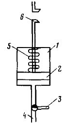
Rice. 4. Pneumatic drive
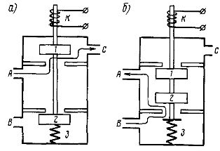
Rice. 5. Switching on (a) and switching off (b) solenoid valves
The cylinder of the pneumatic actuator connected to port A is connected through the open valve 1 to the atmosphere through port C. When the coil K is energized, the solenoid rod presses the upper valve 1 and, overcoming the force of the spring 3, closes valve 1 and opens the valve 2. At the same time, the compressed air from port B through valve 2 and port A into the pneumatic actuator cylinder.
On the contrary, the shut-off valve, when the coil is not excited, connects the cylinder to the compressed air, and when the coil is excited - to the atmosphere. In the initial state, valve 1 (Fig. 5, b) is closed, and valve 2 is open, creating a path for compressed air from port B to port A through valve 2.When the coil is energized, valve 1 opens, connecting the cylinder to the atmosphere, and the air supply is stopped by valve 2.
Electric motor drive
To drive a number of electrical devices, electric motors are used with mechanical systems that convert the rotary motion of the motor shaft into the translational motion of the contact system. The main advantage of electromotor drives compared to pneumatic ones is the constancy of their characteristics and the possibility of their adjustment. According to the principle of operation, these drives can be divided into two groups: with permanent connection of the motor shaft with an electric device and with periodic connection.
In an electric device with an electric motor (Fig. 6), the rotation from the electric motor 1 is transmitted through a gear wheel 2 to the camshaft 3. In a certain position, the cam of the shaft 4 lifts the rod 5 and closes the movable contact associated with it with the stationary contact 6.
In the drive system of group electrical devices, devices are sometimes introduced that provide stepwise rotation of the shaft of an electrical device with a stop in any position. During braking, the engine is switched off. Such a system ensures accurate fixation of the shaft of the electrical apparatus in position.
As an example, FIG. 7 is a schematic illustration of the so-called Maltese cross drive used in group controllers.
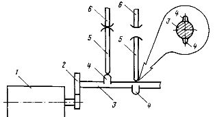
Rice. 6. Electric motor drive with permanent connection of motor shafts and electrical apparatus
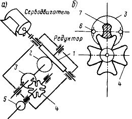
Rice. 7. Electric motor drive of the group controller
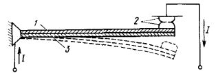
Fig. 8. Thermal actuator with bimetallic plate.
The drive consists of a servo motor and a worm gearbox with position fixing by means of a Maltese cross. The worm 1 is connected to the servomotor and transmits rotation to the shaft of the worm wheel 2, driving the disk 3 with fingers and a latch (Fig. 7, a). The shaft of the Maltese cross 4 does not rotate until the finger of the disk 6 (Fig. 7, b) enters the groove of the Maltese cross.
With further rotation, the finger will rotate the cross, and therefore the shaft on which it sits, by 60 °, after which the finger will be released, and the locking sector 7 will precisely fix the position of the shaft. When you turn the worm gear shaft one turn, the Maltese cross shaft will turn 1/3 turn.
Gear 5 is mounted on the shaft of the Maltese cross, which transmits rotation to the main camshaft of the group controller.
Thermal drive
The main element of this device is bimetallic plate, which consists of two layers of dissimilar metals firmly bonded over the entire contact surface. These metals have different temperature coefficients of linear expansion. A metal layer with a high coefficient of linear expansion 1 (Fig. 8) is called a thermoactive layer, in contrast to a layer with a lower coefficient of linear expansion 3, which is called thermopassive.
When the plate is heated by a current passing through it or by a heating element (indirect heating), a different elongation of the two layers occurs and the plate bends towards a thermopassive layer. With such bending, contacts 2 connected to the plate can be directly closed or opened, which is used in thermal relays.
Bending the plate can also release the lever latch on the electrical apparatus, which is then released by the springs. The set drive current is controlled by selecting heating elements (with indirect heating) or by changing the contact solution (with direct heating). The time to return the bimetallic plate to its original position after operation and cooling varies from 15 s to 1.5 minutes.