Repair of separate assemblies and parts of oil switches
Actuator repair (see Fig. 1).
 Check, clean the shaft 2 and the bearings 12. Check for cracks in the bearings. Clean the lubrication hole 15. The shaft should not have a longitudinal stroke of more than 0.5 — 1 mm. Otherwise, the shaft is removed for repair. To do this, the two-armed lever 3, sitting on the shaft, is previously disassembled, with the transmission rod and from the drive, and the rollers are released, which connect the upper ears of the stop springs and the lever. The rollers are removed, the nuts are unscrewed and the bolts 14 are removed, which fasten the bearings to the frame 1.
Through the cutouts 13 in the frame, the shaft 2 is removed together with the bearings. The bearings are removed from the shaft and washers 18 of the required dimensions are placed on the shaft. Clean the shaft key 17 and the bearing. The shaft is then assembled together with the bearings and installed in the reverse order. A probe is used to check the size of the gap between the shaft shoulder and the end of the bearing, which should be within 0.5 — 1 mm for each bearing.If there is no gap, it is necessary to loosen the nuts of the bolts 14 and put the required thickness of the gasket between the frame and the bearing. Next, check the places where the levers are welded to the shaft. There should be no cracks. The bumper stop roller on the middle lever should rotate freely.
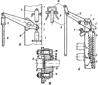
Rice. 1. Actuator: a — breaker VMG-10, b — the same, VMG-133, c — bearing, 1 — frame, 2 — shaft, 3 — two-arm lever, 4 — oil buffer, 5 — spring buffer , 6 — opening spring, 7 — locking bolt, 8 — movable contact, 9 — axis, 10 — clamp, 11 — insulating lever (porcelain rod), 12 — bearing, 13 — cutout in the frame for installing the shaft, 14 — bolt with nut and washer, 15 — hole for grease, 16 — washers, 17 — shaft
It is necessary to carefully check and check the condition of the buffer and the opening springs of the breaker VMG-10 (Fig. 2). The springs should not have cracks in the places where they are welded to the ears, on the surface of the bends, the handle should not have breaks in the threads. The spring tension is adjusted with nut 8. The adjusted distance H is fixed with counter nut 6. The damaged spring is replaced. The frictional parts of the mechanism are lubricated with CIATIM-201 grease.
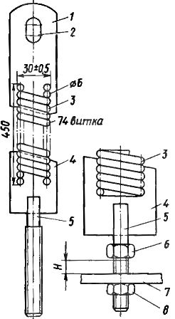 Rice. 2. The opening spring of the circuit breaker VMG -10: 1 — upper stop, 2 — hole for the connecting axis, 3 — spring, 4 — lower lug, 5 — threaded handle, 6 — lock nut, 7 — corner of the frame, 8 — tension nut
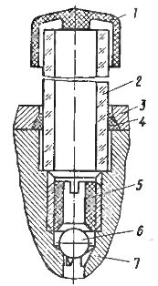
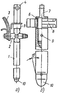
Oil buffer repair (see fig. 3).
Check the stroke of the piston 5 of the buffer, acting with your hand on the rod 4, pressing the piston to the lowest position until it stops at the bottom of the housing 7.The piston under the action of the spring 6 should rise to its original position. In case of jamming or other anomalies in the operation of the buffer, it is disassembled. Unscrew special nut 3, remove the rod, piston and spring, pour oil from the body.
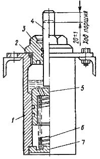
Rice. 3. Oil buffer of the breaker VMG -10: 1 — housing, 2 — sealing gasket, 3 — special nut, 4 — rod, 5 — piston, 6 — spring, 7 — bottom of the housing
All parts are checked and cleaned. Rust and unevenness are sanded.
Repair of oil indicator VMPP-10 (Fig. 4).
Rice. 4. Pressure gauge VMPP -10: 1 — cap, 2 — glass tube, 3 — flange, 4 — gasket, 5 — fitting, b — ball, 7 — body
If a malfunction was noticed when draining the oil, the pressure gauge is disassembled, for which the cap 1, glass tube 2 and gasket 4 are removed, and then (for VMG-133) the rod is removed and the channel in the housing 7 is blown. Assemble the oil indicator in the reverse order. In the VMG-10 switch, a window is made instead of an oil indicator.
Bushing Repair (Fig. 5).
To check and replace damaged parts of the insulator, it is disassembled. The bolts securing the bracket to the cap 4 are unscrewed and the bracket is removed. Remove the washer 6 and bushing 8. Loosen the bolts (for VMG-133) of the semi-manifolds 9, remove the semi-manifolds. By pressing upwards, remove the tube 3 and separate the sleeve 8 with washers 15 and 19.
Remove the half-ring (half-collar) 17 and the spring 16. The insulator is assembled in the reverse order. Check the leather cuffs 8 and 18, which should be sufficiently elastic and elastic, check the fastening of the half-splitters 17.If the pressure spring 16 has windings pressed against each other, it is replaced with a new one, because at high currents the spring forms a closed loop, overheats, and this can lead to carbonization of the bakelite tube 3 and cuffs. For the same reason, the clamping screws of the half-disconnectors must be made of brass.
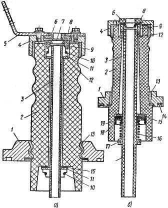
Rice. 5. Bushing insulators for switches: a — VMG -10, b — VMG -133, 1 — flange, 2 — porcelain insulator, 3 — bakelite tube, 4 — cap, 5 — clamp with current, 6 — ring (formed washer ), 7, 15 and 19 — washers. 8 — leather cuff, 9 — sleeve, 10 — half ring, 11 — spring ring, 12 — gasket, 13 — reinforcing putty, 14 — groove in the flange with a sealing gasket, 16 — spring, 17 — half-collar, 18 — bottom leather seal
For the VMG-10 circuit breaker, the insulator disassembly procedure is similar. The insulator is released from the bolt connections, the bracket 5 is removed, the intermediate insulating parts are taken out — ring 6, washer 7, sleeve 8, sleeve 9. Remove the spring and tighten 10 half rings, remove the rubber washer 5. Replace the worn parts. The insulator is then assembled in reverse order.
Repair of insulating bars and rods.
During the inspection, attention is paid to the state of welding of the lugs to the caps of the heat insulator VMG-133. There should be no cracks in these places. The reinforcing joints of the bars are cleaned and painted with oil paint to create a moisture-resistant film.
Crushed porcelain rods, bushings or supporting insulators with an area of 1.1 — 1.5 cm2 are cleaned and coated with insulating varnish (Bakelite). If a larger area is cut, the insulators are replaced. The insulating arms and rods must not be damaged by the paint surface.
Repair of the arc chute (Fig. 6).
In case of soot contamination, in the presence of a small flow of metal on the working surfaces, surface charring of the partitions, which does not increase the cross-section of the blowing channels, it is enough to clean these surfaces with fine sandpaper, rinse with transformer oil and wipe with rag. Tighten the drawbar clamping nuts and check that there are no gaps between the individual plates. Warped and warped plates have been replaced.
Check bottom plate 1 which should be fiber. Increasing the inner diameter of the fiber insert to a value of 28 — 30 mm (for VMG-10), increasing the opening in the partitions between the first and second slots to 3 mm to the exhaust channels is unacceptable. Defective parts are replaced with new ones.
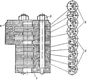
Rice. 6. Arc extinguishing chamber of the circuit breaker VMG -10: 1 — fiber ring, 2 — transverse blowing channels, 3 — pockets, 4 — fiber ring, 5 — textolite connections with nuts
After tightening the bolts, check the height of the cam slots, which should be in accordance with the factory instructions.
When restoring the chamber with the replacement of plates, it is necessary: unscrew the clamping nuts 5, remove the required number of plates from the pullers, install a new plate and place the removed plates in the order in which they were installed before disassembly, and then tighten the clamping nuts. After the chamber partition is checked for protruding edges and irregularities in the central opening for the passage of the movable contact. Burrs and raised edges should be trimmed and removed.
Repair of a fixed female contact (Fig. 7).
If the lamellas of the socket contact have melting or small beads of metal, it is enough to clean them.The dimensions of the lamellae should not differ from the factory ones by more than 0.5 mm. After removing the lamellae, no voids with a depth of more than 0.5 mm should remain. It is recommended to replace more damaged lamellas with less damaged ones. In the presence of strong cavities and due to burns of the refractory lining, the lamellas are replaced.
Bakelite ring 4 must not have delamination and cracks, otherwise it will be replaced. Replacement with a metal ring is not allowed, as it will create a short circuit and cause overheating at high currents. Springs 6 must be free of cracks and voids.
The disassembly of the socket contact is carried out in the following sequence:
-
remove the screws from ring 4,
-
holding the output, remove the ring 4 until the springs 6 fall out,
-
unscrew the bolts 7 that disconnect the lamellae from the flexible links 8 and the flexible links from the base of the socket,
-
remove the support ring 3.
When assembling the socket contact, you should pay attention to the fact that in the assembled contact the lamellae are installed without distortions and are in an inclined position relative to the axis of the socket, touching each other at the top.
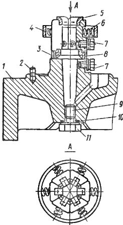
Figure 7. Fixed contact with socket of VMG-10 and VMPP-10 switches: 1 — cover, 2 — retainer, 3 — support ring, 4 — ring, 5 — lamellae, 6 — spring, 7 — screw (bolt), 8 — flexible connection, 9 — oil drain plug, 10 — gasket, 11 — oil drain bolt.
Check the spring pressure on the slats and measure the force required to pull the socket from a 22mm copper rod inserted into the socket. A 0.5 kg disc is attached to the rod, and when the socket is lifted, it must hold this weight by compressing the springs on the slats.
Repair of movable contacts (see fig. 8).
Rice. 8. Movable contact: a — switch VMG -10, b — the same, VMPP -10, 1 — rod, 2 -pin block, 3 — flexible connection, 4 — ears with ears, 5 — lock nut, 6 — sleeve, 7 — head, 8 — guide block, 9 — pin, 10 — tip
When replacing the tip 10 of the movable contact, the new tip must be screwed in all the way so that there is no gap between the tip and the rod. The joint in four places must be tightly sealed. Roll the surface of the joint with a smooth roller, grind the tip. In case of significant damage to the copper part of the rod, the latter is replaced with a new one.
Repair of the contact part.
In the presence of melting, voids, dirt and corrosion, the contact surface is cleaned with gasoline and applied with a file without distorting the profile of the contact part.
Tinned galvanized or silver contact parts are wipe only.
Repair of internal insulation of the tank.
Cracked lower and upper insulating cylinders are replaced. Bakelite tube should not have burns, delamination and cracks. Soot contamination is washed away with transformer oil. In case of scratches or burns, the damaged areas are wiped with a swab dipped in pure aviation gasoline, sanded and covered with air-dried varnish (Bakelite, Glyphtal).
Actions after repairing oil switches
After repair and replacement of defective parts, the switch is assembled in reverse order. The VMG-10 switch, unlike the VMG-133, is easier to assemble: some of the elements (socket contact) are installed from below, and the rest - from the top of the cylinder. The distance between the top of the VMG-133 socket contact and the bottom of the arc chute is 14-16mm.
If the gap deviates from the required value, it is necessary to install additional spacers or to reduce the height of the support ring of the female contact. For VMG-10, this gap is 2-5 mm and is determined by direct measurement. When installing the upper insulating cylinder, check the alignment of the holes in the insulating and main cylinder. Adjust the travel of the movable contact, which should, when in the "on" position, enter the contact of the VMG-10 socket by 40 mm under the action of its own your weight If necessary, eliminate the spasm of the moving stroke of contact. Adjust the full stroke of the movable contact, which should be equal to 210 5 mm.
After adjusting the contact system, the switch is filled with oil (up to 1.5 — 1.6 kg per cylinder).