Mixed connection and complex electrical circuits
 In electrical circuits, a mixed connection, which is a combination of series and parallel connections, is quite common. If we take for example three devices, then two variants of the mixed connection are possible. In one case, two devices are connected in parallel, and a third is connected in series to them (Fig. 1, a).
Such a circuit has two sections connected in series, one of which is a parallel connection. According to another scheme, two devices are connected in series, and a third is connected in parallel with them (Fig. 1, b). This circuit should be considered as a parallel connection where one branch is itself a series connection.
With a larger number of devices, there may be different, more complex mixed connection schemes. Sometimes there are more complex circuits containing several sources of EMF.
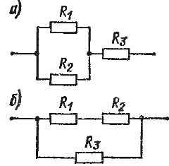
Rice. 1. Mixed connection of resistors
There are various methods for calculating complex circuits. The most common of these is the application Kirchhoff's second law... In its most general form, this law states that in any closed loop the algebraic sum of the EMF is equal to the algebraic sum of the voltage drop.
It is necessary to take an algebraic sum, since EMFs acting towards each other or voltage drops created by oppositely directed currents have different signs.
When calculating a complex circuit, in most cases, the resistances of individual sections of the circuit and the EMF of the included sources are known. To find the currents, in accordance with Kirchhoff's second law, closed-loop equations must be formulated in which the currents are unknown quantities. To these equations it is necessary to add the equations for the branch points, drawn up according to Kirchhoff's first law. Solving this system of equations, we determine the currents. Of course, for more complex schemes, this method turns out to be quite cumbersome, since it is necessary to solve a system of equations with a large number of unknowns.
The application of Kirchhoff's second law can be shown in the following simple examples.
Example 1. An electric circuit is given (Fig. 2). The EMF sources are equal to E1 = 10 V and E2 = 4 V, and internal resistance r1 = 2 ohms and r2 = 1 ohms respectively. The EMFs of the sources act towards each other. Load resistance R = 12 Ohm. Find current I in the circuit.
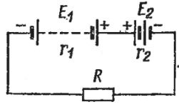
Rice. 2. An electric circuit with two sources connected to each other
Answer. Since there is only one closed loop in this case, we form a single equation: E1 — E2 = IR + Ir1 + Ir2.
On its left side we have the algebraic sum of the EMF, and on the right — the sum of the voltage drop created by the current Iz of all the series-connected sections R, r1 and r2.
Otherwise, the equation can be written in this form:
E1 — E2 = I (R = r1 + r2)
or I = (E1 — E2) / (R + r1 + r2)
Substituting the numerical values, we get: I = (10 — 4)/(12 + 2 + 1) = 6/15 = 0.4 A.
This problem, of course, can be solved based on Ohm's law for the entire circuit, given that when two sources of EMF are connected to each other, the effective EMF is equal to the difference E1- E2, the total resistance of the circuit is the sum of the resistances of all connected devices.
Example 2. A more complex scheme is shown in fig. 3.
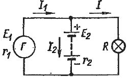
Rice. 3. Parallel operation of sources with different EMFs
At first glance, it seems quite simple. Two sources (for example, a DC generator and a storage battery are taken) are connected in parallel and a light bulb is connected to them. The EMF and internal resistance of the sources are respectively equal: E1 = 12 V, E2 = 9 V, r1 = 0.3 Ohm, r2 = 1 Ohm. Bulb resistance R = 3 Ohm It is necessary to find currents I1, I2, I and voltage U at the source terminals.
Since the EMF E1 more than E2, in this case the generator E1 obviously charges the battery and powers the bulb at the same time. Let's set up the equations according to Kirchhoff's second law.
For a circuit consisting of both sources, E1 — E2 = I1rl = I2r2.
The equation for a circuit consisting of a generator E1 and a light bulb is E1 = I1rl + I2r2.
Finally, in the circuit that includes the battery and the bulb, the currents are directed toward each other, and therefore for it E2 = IR — I2r2.These three equations are insufficient to determine currents because only two of them are independent and the third can be obtained from the other two. Therefore, you need to take two of these equations and as a third write an equation according to Kirchhoff's first law: I1 = I2 + I.
Substituting the numerical values of the quantities in the equations and solving them together, we get: I1= 5 A, Az2 = 1.5 A, Az = 3.5 A, U = 10.5 V.
The voltage at the terminals of the generator is 1.5 V less than its EMF, because a current of 5 A creates a voltage loss of 1.5 V at the internal resistance r1 = 0.3 Ohm. But the voltage at the battery terminals is 1.5 V greater than its emf, because the battery is charged with a current equal to 1.5 A. This current creates a voltage drop of 1.5 V across the internal resistance of the battery ( r2 = 1 Ohm), it is added to the EMF.
You should not think that the stress U will always be the arithmetic mean of E1 and E2, as it turned out in this particular case. One can only argue that in any case U must lie between E1 and E2.