Phase sensitive FUS protection
 Phase-sensitive protection shuts down a three-phase motor in the event of a large voltage imbalance or phase failure.
Phase-sensitive motor protection devices FUZ-M and FUZ-U
Figure 1 shows a diagram of such protection of the FUZ-U type. The device combines phase, current and temperature principles to detect emergency modes. FUZ-U contains phase-changing current transformers TV1 and TV2, phase-ring detector Vd1 -VD4 and R1 — R4, executive relay KV, controlled rectifier with temperature correction VS1 and R5 — R9, charge-discharge circuit R10, VD7, R11, R12, storage capacitor C1, threshold elements VT, VD6, R13, C2, VD5 and R14, thyristor VS2.
The scheme works as follows. When the electric motor operates in an unacceptable mode (two-phase), the phase angle between the voltages of the secondary windings of the transformers TV1, TV2 becomes equal to 0 ° or 180 °, as a result of which the current in the KV relay increases sharply, the relay picks up and turns off the electromagnetic starter to control the motor with its contact open.
To protect the electric motor from overloading, the voltage of the secondary winding of the current transformer is monitored, which is proportional to the load current. At normal load and temperature of the electric motor, the thyristor of the controlled rectifier VS1 is closed and the voltage on the capacitor C1 is not.
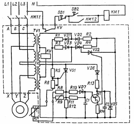
Rice. 1. Electrical diagram of the FUZ-U protective device and its connection diagram
With a certain overload, when the measured voltage reaches the opening threshold of the thyristor VS1, set by the potentiometer R6, the capacitor C begins to charge.1 through the thyristor and the charging resistor R11.
The opening angle of the thyristor depends on the measured voltage, so the charging time of the capacitor is shorter with large overloads. To reduce the response time of the device at very large overloads (silence of the rotor of the electric motor), the charging resistor R11 is manipulated by an additional circuit R11, VD7 and R10
With a large overload, the zener diode VD7 "breaks" and the charging of the capacitor passes through the parallel resistors R10 and P11, providing a delay of no more than 5 — 6 seconds.
When the voltage in the storage capacitor reaches the voltage at the turn-on of the single-transistor VT, the capacitor C1 it quickly discharges through it and opens the thyristor VS2 with a current pulse, which leads to an imbalance in the bridge of the ring detector, a current appears in the KV coil and the motor turns off.
Installing an R7 PTC thermistor on the motor housing provides additional protection in the event of a motor cooling failure.With dangerous overheating of the electric motor, the resistance of the posistor increases sharply, the potential of the base of the thyristor VS increases1, it opens completely, capacitor C1 charges quickly and the motor is turned off.
Thermistor R9 (with a negative temperature coefficient of resistance) is installed in the protection device and is designed to stabilize the protection characteristic when the ambient temperature fluctuates.
Image 2 shows the protective performance of FUZ-U at ambient temperatures of 40 °C (solid line) and 20 °C (dashed line). The characteristics show the high temperature stability of the device.
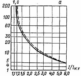
Rice. 2. Protective characteristics of the protective device FUZ-U
The merits of phase-sensitive protection FUZ-U are as follows:
-
quick reaction in direct emergency modes, such as phase failure and non-activation (silencing) of the electric motor;
-
stability of protective characteristics;
-
simplicity of its connection and adjustment of the relay.
Phase-sensitive protective devices FUZ-M, FUZ-U make in five standard sizes with a range of operating currents of electric motors from 1 to 32 A. These devices can be selected according to the rated current of the electric motor.