Linear and non-linear elements of the electric circuit
Linear elements
Those elements of the electric circuit, for which the dependence of the current on the voltage I (U) or the voltage on the current U (I), as well as the resistance R, are constant, are called linear elements of the electric circuit. Accordingly, a circuit consisting of such elements is called a linear electrical circuit.
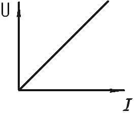
Linear elements are characterized by a linearly symmetrical current-voltage characteristic (CVC), which resembles a straight line passing through the origin at a certain angle to the coordinate axes. This shows that for linear elements and for linear electric circuits Ohm's Law strictly observed.
In addition, we can talk not only about elements with purely active resistances R, but also about linear inductances L and capacitances C, where the dependence of the magnetic flux on the current — Ф (I) and the dependence of the capacitor charge on the voltage between its plates — q (U).
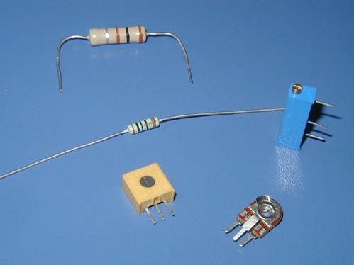
A prime example of a linear element is coiled wire resistor… The current through such a resistor in a certain operating voltage range depends linearly on the value of the resistance and on the voltage applied to the resistor.
Conductor characteristic (current-voltage characteristic) — the relationship between the voltage applied to the wire and the current in it (usually expressed as a graph).
For a metal conductor, for example, the current in it is proportional to the applied voltage, and therefore the characteristic is a straight line. The steeper the line, the lower the resistance of the wire. However, some conductors in which the current is not proportional to the applied voltage (for example, gas discharge lamps) have a more complex, non-linear current-voltage characteristic.
Non-linear elements
If for an element of an electric circuit the dependence of the current on the voltage or the voltage on the current, as well as the resistance R, are not constant, i.e. they change depending on the current or on the applied voltage, then such elements are called non-linear and, accordingly, an electric circuit , containing at least one nonlinear element, turns out non-linear electric circuit.
The current-voltage characteristic of a non-linear element is no longer a straight line on the graph, it is non-linear and often asymmetric, such as a semiconductor diode. Ohm's law is not fulfilled for non-linear elements of an electrical circuit.
In this context, we can talk not only about an incandescent lamp or a semiconductor device, but also about non-linear inductances and capacitors, where the magnetic flux Φ and charge q are non-linearly related to the coil current or to the voltage between the plates of the capacitor. Therefore, for them the Weber-ampere characteristics and the Coulomb-volt characteristics will be non-linear, they are set by tables, graphs or analytical functions.
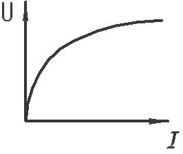
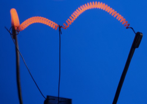
An example of a non-linear element is an incandescent lamp. As the current through the filament of the lamp increases, its temperature increases and the resistance increases, which means that it is not constant and therefore this element of the electrical circuit is non-linear.
Static resistance
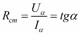
For non-linear elements, a certain static resistance is characteristic at each point of their I — V characteristic, that is, each voltage-to-current ratio at each point of the graph is assigned a certain resistance value. It can be calculated as the tangent of the angle alpha of the slope of the graph to the horizontal I-axis as if this point lies on a line graph.
Differential resistance
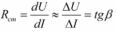
Nonlinear elements also have a so-called differential resistance, which is expressed as the ratio of an infinitesimally small increase in voltage to the corresponding change in current. This resistance can be calculated as the tangent of the angle between the tangent to the I — V characteristic at a given point and the horizontal axis.
This approach makes the analysis and calculation of simple nonlinear circuits as simple as possible.
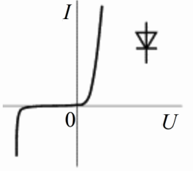
The figure above shows the I — V characteristic of a typical diode… It is located in the first and third quadrants of the coordinate plane, this tells us that with a positive or negative voltage applied to the pn-junction of the diode (in one direction or the other), there will be forward or reverse bias from the pn-junction of the diode. As the voltage across the diode increases in either direction, the current initially increases slightly, and then increases sharply. For this reason, the diode belongs to an uncontrolled nonlinear bipolar network.
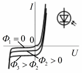
This figure shows a family with typical I — V characteristics. photodiode under different lighting conditions. The main mode of operation of the photodiode is the reverse bias mode, when at a constant light flux Ф the current practically does not change in a fairly wide range of operating voltages. Under these conditions, modulation of the light flux illuminating the photodiode will result in a simultaneous modulation of the current through the photodiode. Thus, the photodiode is a controlled nonlinear bipolar device.
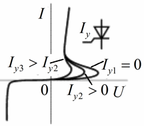
This is VAC thyristor, here you can see its clear dependence on the magnitude of the control electrode current. In the first quadrant — the working section of the thyristor. In the third quadrant, the beginning of the I — V characteristic is a small current and a large applied voltage (in the closed state, the resistance of the thyristor is very high). In the first quadrant, the current is high, the voltage drop is small — the thyristor is currently open.
The moment of transition from closed to open state occurs when a certain current is applied to the control electrode. The transition from the open state to the closed state occurs when the current through the thyristor decreases.Thus, the thyristor is a controlled non-linear three-pole (like a transistor where the collector current depends on the base current).