What is electric damping, damper coils and coils
Amortization — increasing energy losses in the system in order to increase the damping of oscillations in it.
Mechanical damping
Depreciation applied in measuring devices to reduce pointer arrow jitter in other devices as well. Mechanical damping is achieved by increasing friction or increasing the resistance of the medium in which the system moves. For example, a light piston is attached to the rotating system of the device, which moves in the tube, slowing down the movement of the moving system.
Electrical devices with moving parts always have braking devices in one form or another, since the motion of the moving part must be stopped somewhere and the store of kinetic energy absorbed. First of all, in any moving system there are frictional forces always directed against the motion.
If the kinetic energy is large, they resort to special braking devices in which the excess kinetic energy is absorbed.In a number of devices (for example, in relays), the braking devices are designed not only to absorb the excess kinetic energy of the moving parts (when they approach the closure to avoid a strong shock), but also to slow down the action of the device.
In the first case, when the braking device is designed only to absorb excess kinetic energy at the end of the stroke, it is usually called a buffer device, and in most cases, when this device starts to work, the force moving the parts of the apparatus stops. In the second case, the braking device acts during the existence of the driving force in the apparatus and is called shock absorber.
Depreciation in electrical devices
Electric damping can take place by interaction between the magnetic field and the currents induced in wires moving in this magnetic field, because according to Lenz's law in this case there must always be a force that prevents this movement. For example, a moving plate of conductive material is attached to the movable system of the device between the poles of a magnet… In this case, eddy currents arise in it, the interaction of which with the magnetic field slows down the movement of the system.
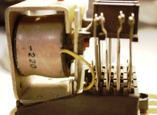
Shock absorber coils — includes the magnetic circuit that serves to dampen the moving part of the magnetic system. For example, such turns of copper are installed on the magnetic circuit of a magnetic starter or contactor from the edges of the contact planes of the armature and the core.
Any alternating current electromagnet has a time-varying pulling force, and at times when the magnetic flux passes through zero, it is also zero.This circumstance leads to the fact that the armature of the electromagnet cannot be stable in its final position, and under the action of opposing forces in the region of zero flux, the armature and its associated parts tend to move backwards.
The rapidly increasing force of the anchor pull does not allow these parts to separate from the stop for a significant distance, but they still move a short distance. As a result, the parts of the apparatus pressed by the anchor to the limiter are not in a stationary position, but vibrate in time with the pulling force of the electromagnet.
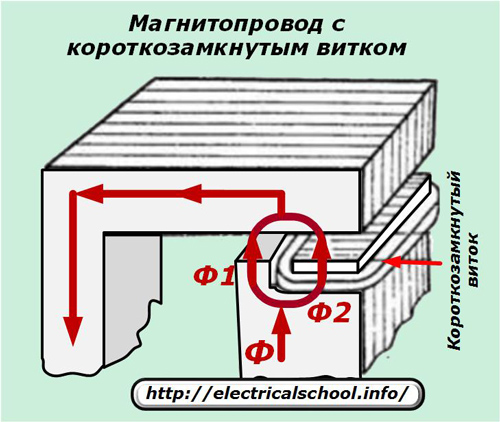
This causes the rattling of these parts, loosening of the mechanism, wear of the contacts pressed by the electromagnet, noise and other unpleasant consequences. One of the common measures to combat this phenomenon is the use of a short circuit covering part of the main section.
In this case, the part of the flux penetrating the short-circuited coil does not coincide in phase with the other part of the flux, and therefore the zero value of the traction force of the fluxes does not coincide in time. As a result, a given AC electromagnet will not have a point in time where its pulling force is zero and the indicated rattling will be absent. Usually the number of turns of a short circuit is equal to one and it is called accordingly short circuit.
In some designs of direct current electromagnets, a special short circuit winding with low electrical resistance is applied to the core (or to the armature).This is then done to slow down the operation of the electromagnet: in the presence of such a coil, the increase in flux after turning on the coil or voltage and flux after turning off the current is slower than without such a coil.
The influence of such a coil will be reflected not only when the armature is stationary during an unsteady flux process, but also when the armature is moving, when due to a change in the air gap, the flux in the electromagnet tends to change. This physical process is called magnetic damping.
The use of an additional winding for the purposes of damping processes in an AC electromagnet does not achieve the objectives and is therefore not used.
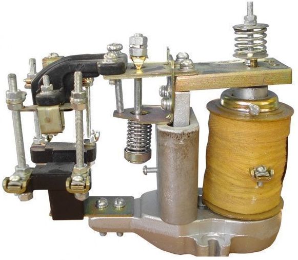
Magnetic damping is often used to delay the operation and release of electromagnetic and DC synchronizing relays. This slows the rise and fall of the magnetic flux in the core. For this purpose, short circuits are placed on the magnetic circuit of the relay. Thanks to this technical solution, a delay of 0.2 to 10 seconds is obtained. Sometimes magnetic damping is done not by using a short circuit, but by shorting the working coil of the relay.
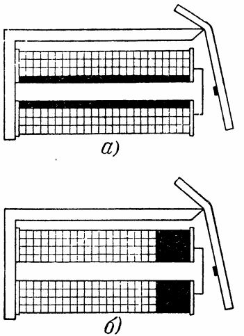
Electromagnetic relays with magnetic damping: a — with a copper sleeve; b — with a copper ring in the working gap.
There are a number of practical cases where the operating time of electromagnets and electromagnetic devices (relays, starters, contactors) must be as short as possible.In this case, the presence of short-circuited windings, massive parts of the magnetic circuit, metal frames of the coil and short circuits formed by fasteners and other parts of the apparatus lying in the path of the flow are unacceptable, since they will increase the time for operation of the electromagnet.
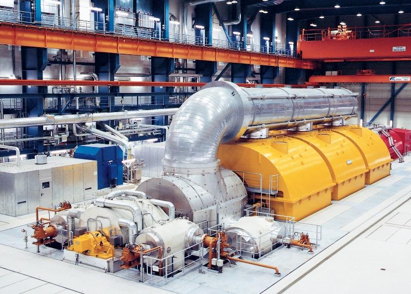
Depreciation in electrical machines
Almost all synchronous motors, compensators and convertersand many salient-pole synchronous generators are equipped with damping windings. In some cases they are used because of the effect on system stability, but for the most part they are intended for other purposes. However, regardless of the reasons for using damping coils, they affect stability to a greater or lesser extent.
There are basically two types of damping coils: full or closed and incomplete or open. In both cases the winding consists of rods laid in grooves on the surface of the poles, the ends of which are connected on each side of the pole.
With a full damping coil, the ends of the rods are closed with rings connecting the rods at all poles. In incomplete winding, the rods are closed with arcs, each of which connects the rods at only one pole. In the latter case, the damping coil of each pole is an independent circuit.
Full soothing coils are like squirrel cells of asynchronous machine rotors, except that in damping coils the bars are unevenly spaced around the circumference of the rotor because there are no bars between the poles. In some designs, the end rings are made of separate sections that are bolted together to facilitate pole removal.
Damper coils can be classified according to their active resistance. Low resistance coils produce the most torque at low slip and high resistance coils at high slip. Sometimes a coil with double damping is used. It consists of coils with low and high inductive resistance. Double damping coils are used to improve the starting characteristics of synchronous motors and make it easier for them to get in sync.
The purpose of damping coils for synchronous machines:
-
Increasing the starting torque of synchronous motors, compensators and converters;
-
Prevent swaying. Damping coils were first made for this purpose, and hence received their name;
-
Suppression of oscillations resulting from shocks during short-circuiting or switching;
-
Prevention of distortion of the voltage waveform by an unbalanced load, in other words — suppression of higher harmonic components;
-
Reducing the unbalance of the phase voltage of the terminals with an unbalanced load, i.e. negative sequence voltage reduction;
-
Prevention of overheating of the surface of the poles of single-phase generators by eddy currents;
-
Creating a braking torque in the generator in case of asymmetric short circuits and reducing this excess torque;
-
Creating an additional moment when synchronizing generators;
-
Reducing the speed of voltage recovery in the switch contacts;
-
Reduction of mechanical stresses in the field winding insulation during inrush currents in the armature circuit.
Generators driven by reciprocating prime movers tend to wobble due to the pulsating torque of the prime movers. Electric motors driving pulsating torque loads such as compressors also tend to oscillate.
These swings are called "forced swings". It is also possible for "spontaneous oscillations" to occur when synchronous machines are connected through a line where the ratio of active resistance to inductive resistance is large.
Low resistance damping coils significantly reduce the amplitudes of both forced and spontaneous oscillations.
The influence of damping (damper coils) on the stability of electrical systems is manifested in the fact that they:
-
Creating an amortizing (asynchronous) moment of direct sequence;
-
Creates a reverse sequence braking torque during asymmetric short circuits;
-
By changing the impedance of the negative sequence, the electrical power of the positive sequence is affected by the machine during asymmetric short circuits.