The device and principle of operation of asynchronous electric motors
Electric carsconversion of electrical energy from alternating current to mechanical energy are called AC electric motors.
In industry, asynchronous three-phase motors are the most widespread. Let's look at the device and the principle of operation of these engines.
The principle of operation of the induction motor is based on the use of a rotating magnetic field.
To understand the operation of such an engine, we will perform the following experiment.
We will strengthen horseshoe magnet on the axle so that it can be rotated by the handle. Between the poles of the magnet we place a copper cylinder along the axis, which can rotate freely.
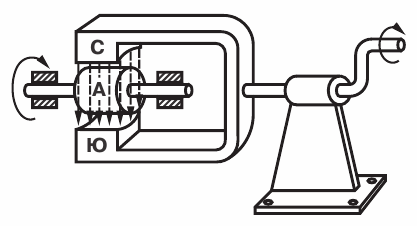
Figure 1. The simplest model for obtaining a rotating magnetic field
Let's start turning the handle magnet clockwise. The field of the magnet will also begin to rotate and, as it rotates, will cross the copper cylinder with its lines of force. In a cylinder according to the law of electromagnetic induction, will have eddy currentswho will create their own magnetic field — the field of the cylinder. This field will interact with the magnetic field of the permanent magnet, causing the cylinder to rotate in the same direction as the magnet.
It was found that the speed of rotation of the cylinder is slightly less than the speed of rotation of the magnetic field.
In fact, if the cylinder rotates at the same speed as the magnetic field, then the magnetic field lines do not cross it and therefore no eddy currents arise in it, causing the cylinder to rotate.
The speed of rotation of the magnetic field is usually called synchronous, because it is equal to the speed of rotation of the magnet, and the speed of rotation of the cylinder is asynchronous (asynchronous). Therefore, the motor itself is called an induction motor... The speed of rotation of the cylinder (rotor) differs from synchronous speed of rotation of the magnetic field with a small amount of slippage.
Denotes the speed of rotation of the rotor through n1 and the speed of rotation of the field through n we can calculate percentage slip by the formula:
s = (n — n1) / n.
In the above experiment we obtained a rotating magnetic field and the rotation of the cylinder caused by it due to the rotation of a permanent magnet, therefore such a device is not yet an electric motor… It should be done electricity create a rotating magnetic field and use it to turn the rotor. This problem was brilliantly solved in his time by M. O. Dolivo-Dobrovolski. He proposed to use three-phase current for this purpose.
The device of an asynchronous electric motor M. O. Dolivo-Dobrovolski
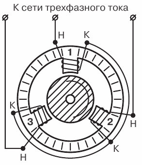
Figure 2. Diagram of Dolivo-Dobrovolsky asynchronous electric motor
On the poles of a ring-shaped iron core, called a motor stator, are placed three windings, three-phase current networks 0 located relative to each other at an angle of 120 °.
Inside the core, a metal cylinder, the so-called rotor of the electric motor.
If the coils are interconnected as shown in the figure and connected to a three-phase current network, then the total magnetic flux created by the three poles will turn out to be rotating.
Figure 3 shows the graph of the changes in the currents in the motor windings and the process of the appearance of a rotating magnetic field.
Let's look at this process in more detail.
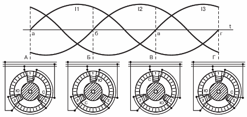
Figure 3. Obtaining a rotating magnetic field
In position «A» of the graph, the current in the first phase is zero, in the second phase it is negative, and in the third it is positive. Current flows through the pole coils in the direction indicated by the arrows in the figure.
Having determined, according to the right-hand rule, the direction of the magnetic flux created by the current, we will ensure that the south pole (S) will be created at the inner pole end (facing the rotor) of the third winding and the north pole (C ) will be created at the pole of the second coil. The total magnetic flux will be directed from the pole of the second coil through the rotor to the pole of the third coil.
 In position «B» of the graph, the current in the second phase is zero, in the first phase it is positive, and in the third it is negative. The current flowing through the pole windings creates a south pole (S) at the end of the first winding and a north pole (C) at the end of the third winding. The total magnetic flux will now be directed from the third pole through the rotor to the first pole, that is, the poles will move by 120 °.
In position «B» of the graph, the current in the third phase is zero, in the second phase it is positive, and in the first phase it is negative.Now the current flowing through the first and second coils will create a north pole (C) at the pole end of the first coil, and a south pole (S) at the pole end of the second coil, i.e. , the polarity of the total magnetic field will shift another 120 °. At position «G» on the graph, the magnetic field will move another 120 °.
Thus, the total magnetic flux will change its direction with a change in the direction of the current in the stator windings (poles).
In this case, for one period of change of current in the coils, the magnetic flux will make a complete revolution. The rotating magnetic flux will drag the cylinder with it and thus we will get an asynchronous electric motor.
Recall that in Figure 3 the stator windings are star-connected, but a rotating magnetic field is formed when they are delta-connected.
If we switch the windings of the second and third phases, the magnetic flux will reverse its direction of rotation.
The same result can be achieved without changing the stator windings, but directing the current of the second phase of the network into the third phase of the stator, and the third phase of the network into the second phase of the stator.
Therefore, you can change the direction of rotation of the magnetic field by switching two phases.
We considered a device with an induction motor with three stator windings... In this case, the rotating magnetic field is bipolar, and the number of revolutions per second is equal to the number of periods of current change in one second.
 If six coils are placed on the stator around the circumference, then a four-pole rotating magnetic field... With nine coils, the field will be six-pole.
At a frequency of three-phase current equal to 50 periods per second or 3000 per minute, the number of revolutions n of the rotating field per minute will be:
with bipolar stator n = (50 NS 60) / 1 = 3000 rpm,
with a four-pole stator n = (50 NS 60) / 2 = 1500 revolutions,
with a six-pole stator n = (50 NS 60) / 3 = 1000 turns,
with the number of pairs of stator poles equal to p: n = (f NS 60) / p,
So, we established the speed of rotation of the magnetic field and its dependence on the number of windings of the stator of the motor.
As we know, the motor rotor will lag a bit in its rotation.
However, the rotor lag is very small. For example, when the engine is idling, the difference in speed is only 3% and under load 5-7%. Therefore, the speed of the induction motor changes within very small limits when the load changes, which is one of its advantages.
Consider now the device of asynchronous electric motors
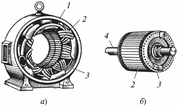
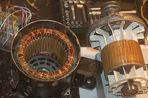
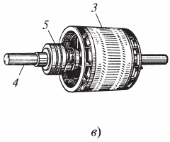 Disassembled asynchronous electric motor: a) stator; b) squirrel-cage rotor; c) rotor in the execution phase (1 — frame; 2 — core of stamped steel sheets; 3 — coil; 4 — shaft; 5 — sliding rings)
The stator of a modern asynchronous electric motor has unpronounced poles, that is, the inner surface of the stator is made completely smooth.
To reduce eddy current losses, the stator core is formed from thin stamped steel sheets.  The assembled stator core is fixed in a steel casing.
A coil of copper wire is laid in the slots of the stator. The phase windings of the stator of the electric motor are connected by a «star» or «delta», for which all the beginnings and ends of the windings are brought to the body - to a special insulating shield. Such a stator device is very convenient, as it allows you to turn on its windings to different standard voltages.
An induction motor rotor, like a stator, is assembled from stamped steel sheets. A coil is laid in the grooves of the rotor.
Depending on the design of the rotor, asynchronous electric motors are divided into squirrel-cage rotor and phase rotor motors.
The squirrel cage rotor winding is made of copper rods inserted into the slots of the rotor. The ends of the rods are connected with a copper ring. This is called squirrel cage rolling. Note that the copper bars in the channels are not insulated.
In some engines, the "squirrel cage" is replaced by a cast rotor.
Asynchronous rotor motor (with slip rings) is generally used in high power electric motors and in these cases; when it is necessary for the electric motor to create a large force when starting. This is achieved by the fact that the windings of the phase motor are connected starting rheostat.
Squirrel cage induction motors are commissioned in two ways:
1) Direct connection of the three-phase mains voltage to the motor stator. This method is the simplest and most popular.
2) Reducing the voltage applied to the stator windings. The voltage is reduced, for example, by switching the stator windings from star to delta.
The motor is started when the stator windings are connected in "star", and when the rotor reaches normal speed, the stator windings are switched to "delta" connection.
The current in the supply wires in this method of starting the motor is reduced by 3 times compared to the current that would occur when starting the motor by direct connection to the network with stator windings connected by «delta».However, this method is only suitable if the stator is designed for normal operation when its windings are delta connected.
The simplest, cheapest and most reliable is an asynchronous squirrel-cage motor, but this motor has some disadvantages — low starting effort and high starting current. These disadvantages are largely eliminated by the use of a phase rotor, but the use of such a rotor greatly increases the cost of the motor and requires rheostat starting.
Types of asynchronous motors
The main type of asynchronous machine is a three-phase asynchronous motor... It has three stator windings located at 120 ° from each other. The coils are star or delta connected and powered by three-phase alternating current.
Low-power motors are in most cases implemented as two-phase... Unlike three-phase motors, they have two stator windings, the currents in which must be offset at an angle to create a rotating magnetic field π/2.
If the currents in the windings are equal in magnitude and shifted in phase by 90 °, then the operation of such a motor will not differ in any way from the operation of a three-phase. However, such motors with two stator windings are in most cases powered by a single-phase network and a displacement approaching 90 ° is created artificially, usually due to capacitors.
Single-phase motor only one winding of the stator is practically inactive. When the rotor is stationary, only a pulsating magnetic field is created in the motor and the torque is zero. It is true that if the rotor of such a machine rotates to a certain speed, then it can perform the functions of an engine.
In this case, although there will be only a pulsating field, it consists of two symmetrical - forward and backward, which create unequal torques - a larger motor and less braking, arising due to the rotor currents of increased frequency (slip against the reverse synchronous field is greater than 1).
In relation to the above, single phase motors are supplied with a second winding which is used as the starting winding. Capacitors are included in the circuit of this coil to create a phase shift of the current, the capacity of which can be quite large (tens of microfarads with a motor power of less than 1 kW).
Control systems use two-phase motors, sometimes called executive... They have two stator windings offset in space by 90 °. One of the windings, called the field winding, is directly connected to a 50 or 400 Hz network. The second is used as a control coil.
To create a rotating magnetic field and the corresponding torque, the current in the control coil must be displaced by an angle close to 90 °. Regulation of the motor speed, as will be shown below, is done by changing the value or phase of the current in this coil. The opposite is provided by changing the phase of the current in the control coil by 180 ° (switching of the coil).
Two-phase motors are produced in several versions:
-
with squirrel cage rotor,
-
with a hollow non-magnetic rotor,
-
with a hollow magnetic rotor.
Linear motors
The transformation of the rotational movement of the engine into the translational movement of the working machine organs is always associated with the need to use any mechanical units: gear racks, screw, etc.only conditionally — as a moving organ).
In this case, the engine is said to be deployed. The stator winding of a linear motor is carried out in the same way as for a volumetric motor, but it should be laid only in the grooves along the entire length of the maximum possible movement of the sliding rotor. The slider rotor is usually short-circuited, the working body of the mechanism is articulated with it. At the ends of the stator there must of course be stops to prevent the rotor from leaving the working limits of the path.