What is electrical impedance?
In DC circuits, the resistance R plays an important role. As for sinusoidal AC circuits, then it cannot be done with only one active resistance. In fact, if in DC circuits the capacities and inductances are noticeable only during transient processes, then in AC circuits these components manifest themselves much more significantly.
Therefore, for an adequate calculation of alternating current circuits, the term «electrical impedance» is introduced - Z or the complex (total) resistance of a two-ended network to a harmonic signal. Sometimes they just say "impedance", leaving out the word "electrical".
The concept of impedance allows you to apply Ohm's law to sections of alternating current sinusoidal current circuits... The manifestation of the double-ended (loading) inductive component leads to the lagging of the current from the voltage at a given frequency, and the manifestation of the capacitive component - to the lagging of the voltage from the current. The active component does not cause a delay between current and voltage, acting in essentially the same way as in a DC circuit.
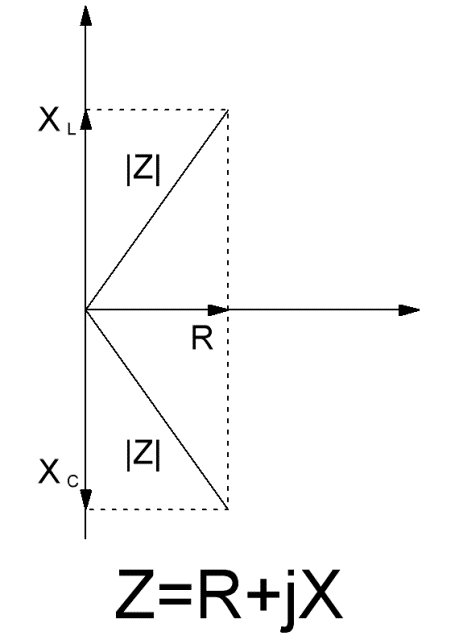
The impedance component containing the capacitive and inductive components is called the reactive component X. Graphically, the active component R of the impedance can be plotted on the oX axis, and the reactive component on the oY axis, then the impedance as a whole will be represented in the form of a complex a number where j is the imaginary unit (the imaginary unit squared is minus 1).

In this case, it is clearly seen that the reactive component X can be decomposed into capacitive and inductive components, which have the opposite direction, that is, have the opposite effect on the current phase: with the predominance of the inductive component, the impedance of the circuit as a whole will be positive, that is the current in the circuit will lag the voltage, but if the capacitive component predominates, then the voltage will lag the current.
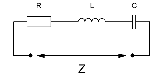
Schematically, this two-terminal network in the given form is depicted as follows:

In principle, any linear two-port network diagram can be reduced to a similar form. Here you can determine the active component R, which does not depend on the current frequency, and the reactive component X, which includes the capacitive and inductive components.

From the graphical model, where the resistances are represented by vectors, it is clear that the modulus of the impedance for a given frequency of sinusoidal current is calculated as the length of the vector, which is the sum of the vectors X and R. Impedance is measured in ohms.

Practically, in the descriptions of sinusoidal AC circuits in terms of impedance, you can find terms such as «active-inductive nature of the load» or «active-capacitive load» or «purely active load». This means the following:
-
If the influence of the inductance L prevails in the circuit, then the reactive component X is positive, while the active component R is small — this is an inductive load. An example of an inductive load is an inductor.
-
If the influence of capacitance C predominates in the circuit, then the reactive component X is negative, while the active component R is small — this is a capacitive load. An example of a capacitive load is a capacitor.
-
If the active resistance R predominates in the circuit while the reactive component X is small, it is an active load. An example of an active load is an incandescent lamp.
-
If the active component R in the circuit is significant, but the inductive component prevails over the capacitive component, that is, the reactive component X is positive, the load is called active-inductive. An example of an active-inductive load is an induction motor.
-
If the active R component in the circuit is significant, while the capacitive component prevails over the inductive component, that is, the reactive component X is negative, the load is called active-capacitive. An example of an active-capacitive load is powering a fluorescent lamp.
See also:What is Power Factor (Cosine Phi)

