Malfunctions of measuring transformers in electrical energy measurement schemes
How to determine the fault of the measuring transformers in the electricity meter circuits
A characteristic sign of a current transformer failure is a discrepancy between the secondary current and the primary. However, the same significant reduction in secondary current can occur in the event of faults and faults in the circuit. Therefore, both the current transformer and its circuit are subject to inspection.
A damaged current transformer can be identified by the following characteristic: the secondary current with the resistance of the secondary circuits close to zero (the winding is short-circuited at the terminal) is much higher than the secondary current at the actual resistance.
Increased load on instrument transformers
The increased load of the measuring transformers, exceeding the permissible for this class of accuracy, introduces an additional negative error (underestimation) in the measurement of electricity consumption.
To experimentally determine the load, the currents and voltages in the secondary circuits are measured simultaneously. Measurements can be made both with operating current and voltage, and with a disconnected voltage supplied from an external source. It is possible to reduce the load on the secondary winding of the current transformer by increasing the cross-section of the cable cores in the current circuits and by disconnecting additional equipment from these circuits
To reduce the load and reduce the error of the voltage transformer, the load should be distributed as much as possible so that the currents in all phases are the same.
It is recommended to distribute the load of voltage transformers connected in open delta as follows. Uca is not connected to voltage. It is distributed as evenly as possible between the voltages Uab and Ubc.
It is necessary to check the possibility of reducing the load by removing additional equipment in the voltage circuits, as well as to check the voltage drop in the wires connecting the voltage transformer to the meter.
Increased voltage drop in voltage circuits
The increased voltage drop in the wires connecting the voltage transformer to the meter causes the negative error to increase. In practice, this can happen if the length of the wire exceeds 15 m.
The voltage drop can be determined empirically. An AC voltmeter with a high internal resistance (1-10 kOhm / V) is suitable for this purpose. The voltmeter is connected to the ends of the core.
Measurement voltage loss, because the difference between the line voltages at the ends of the cable cannot give reliable results. A large error will be introduced by the error of voltmeters, simultaneous readings and other reasons.
To reduce the voltage drop, it is necessary to increase the cross-section of the cable cores. In some cases, it is necessary not to feed the measuring devices from ordinary "voltage bars", but to put a separate cable to them.
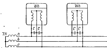
Capacitive inductance compensation gives good results in reducing the voltage drop in the wires connecting the voltage transformer to the meter.

Measurement of the voltage drop in the core of the control cable: / — installation of clamps for a voltage transformer; // — installation of measuring circuit clamps, /// — spare wire

Connection diagram of compensating capacitors in the voltage transformer circuit
If the meters are far from each other, it is recommended to install capacitors separately for each meter. In the case of centralized placement of measuring devices, it is enough to set, capacitor bank.
