Static capacitors for reactive power compensation
Static capacitors are most widely used in industrial enterprises as a means of reactive power compensation. The main advantages of static capacitors for reactive power compensation are:
1) minor losses of active power lying in the range of 0.3-0.45 kW per 100 kvar;
2) the absence of rotating parts and the relatively low mass of the installation with capacitors, and in this respect there is no need for a foundation; 3) more simple and cheap operationfrom other compensatory devices; 4) the possibility of increasing or decreasing the installed capacity, depending on the need; 5) the possibility of installing static capacitors at any point of the network: on individual electrical receivers, on groups in workshops or large batteries. In addition, the failure of an individual capacitor, if properly protected, usually does not affect the operation of the entire capacitor. Classification and technical characteristics of static capacitors for reactive power compensation Static capacitors are classified according to the following criteria: nominal voltage, number of phases, type of installation, type of impregnation, overall dimensions. To compensate for the reactive power of alternating current electrical installations with a frequency of 50 Hz, domestic industry produces capacitors for the following nominal voltages: 220 — 10500 V. Capacitors with a voltage of 220-660 V are available in both single-phase and three-phase (delta-connected sections ), and capacitors with a voltage of 1050 V and more are available only in single-phase. Capacitors with the possibility of performing three-phase capacitor units with a voltage of 3.6 and 10 kV with a star connection scheme. Capacitors with voltages of 1050, 3150, 6300 and 10500 V are used to make three-phase capacitor units with voltages of 1, 3, 6 and 10 kV with delta connection. The same capacitors are used in higher voltage capacitor banks. Depending on the type of installation, capacitors can be produced with all rated voltages for both outdoor and indoor installations. Capacitors for external installations are produced with external insulation (terminal insulators) for a voltage of at least 3150 V. According to the type of impregnation, capacitors are divided into capacitors impregnated with mineral (petroleum) oil and capacitors impregnated with a synthetic liquid dielectric. In terms of size, the capacitors are divided into two dimensions: the first with dimensions of 380x120x325 mm, the second with dimensions of 380x120x640 mm. Types and designations of static capacitors for reactive power compensation Static capacitors are produced in the following types: KM, KM2, KMA, KM2A, KS, KS2, KSA, KS2A, and the classification signs are reflected in the alphanumeric designation of the type. The letters and numbers mean: K — «cosine», M and C — impregnated with mineral oil or synthetic liquid dielectric, A — version for external installation (without letter A — for internal), 2 — version in case of second size (without number 2 — in the case of the first dimension). After designating the type, capacitors are indicated by numbers Rated voltage capacitor (kV) and rated power (kvar). For example: KM-0.38-26 means a "cosine" capacitor (for compensation of reactive power in an alternating current network with a frequency of 50 Hz), impregnated with mineral oil, for indoor installation, first dimension, for a voltage of 380 V, with a power of 26 kvar; KS2-6.3-50-«cosine», impregnated with synthetic liquid, second size, for indoor installation, for voltage 6.3 kV, power 50 kvar.
Static capacitor device for reactive power compensation
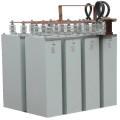 The main structural elements of capacitors are a tank with insulators and a movable part consisting of a battery of sections of the simplest capacitors.
Single-series capacitors rated up to and including 1050 V are manufactured with built-in fuses connected in series with each section. Higher voltage capacitors do not have built-in fuses and must be installed separately. In this case, group protection of capacitors with fuses is carried out.When group protection is carried out in the form of fuses, one fuse protects every 5-10 capacitors, and the rated current of the group does not exceed 100 A. In addition, common fuses are installed for the entire battery.
For capacitors with a voltage of 1050 V and below, with built-in fuses, common fuses are also installed for the battery as a whole, and with significant battery power - for individual sections.
Depending on the mains voltage, three-phase capacitor banks can be supplemented with single-phase capacitors with series or parallel-series connection of capacitors in each phase of the battery.
Connecting capacitor banks to the grid
 Capacitor banks of any voltage can be connected to the network either through a separate device designed to switch capacitors on or off only, or through a common control device with a power transformer, asynchronous motor or other receiver of electricity.
Static capacitors in installations with a voltage of up to 1000 V are connected to the network and disconnected from the network using switches or circuit breakers.
Capacitors used in installations with voltages above 1000 V are connected to the mains and disconnected from the mains only by means of switches or disconnectors (load disconnectors).
So that the costs of turning off the equipment are not too high, it is not recommended to take capacities of capacitor banks less than:
a) 400 kvar at a voltage of 6-10 kV and connecting the batteries to a separate switch;
b) 100 kvar at a voltage of 6-10 kV and connecting the battery to a switch in common with a power transformer or other electrical receiver;
c) 30 kvar at voltages up to 1000 V.
Using discharge resistors with capacitors for reactive power compensation
For safety when servicing disconnected capacitors when removing the electrical charge, it is necessary to use discharge resistors connected in parallel with the capacitors. For the purpose of reliable discharge, the connection of the discharge resistors to the capacitors should be done without intermediate disconnectors, switches or fuses. The discharge resistors must provide a rapid automatic reduction of the voltage across the capacitor terminals.
At the customer's request, the capacitors can be produced with built-in discharge resistors located under the cover of an insulating seal. These resistors reduce the voltage from the maximum operating voltage to 50 V in no more than 1 minute for capacitors with a voltage of 660 V and below and in no more than 5 minutes for capacitors with a voltage of 1050 V and above.
Most capacitors that are already installed in industrial enterprises do not have built-in discharge resistances. In this case, incandescent lamps for a voltage of 220 V. are usually used as a discharge resistance at a voltage of up to 1 kV for capacitor batteries. The connection of lamps connected in series with several parts in each phase is carried out according to the triangular scheme. At voltages above 1 kV, voltage transformers are installed as discharge resistance, which are connected according to the delta or open delta scheme.
Switching circuit of an incandescent lamp for discharging capacitor batteries (up to 1000 V) using a double blade switch
Permanently connecting incandescent lamps, which are usually used as discharge resistors for capacitor banks with voltages up to 660 V, causes unproductive energy losses and lamp consumption.
The lower the battery power, the greater the lamp power per 1 kvar installed capacitors. It is more expedient that the lamps are not connected constantly, but automatically turn on when the capacitor block is turned off. For this purpose, the diagram shown in the figure, in which double knife switches are used, can be used. The additional blades are located in such a way that the lamps turn on before disconnecting the battery from the mains, and turn off after connecting the battery. This can be achieved by choosing an appropriate angle between the main and auxiliary breaker vanes.
When connecting capacitors and electricity receiver directly to the network under the common switch, no special discharge resistances are required. Then capacitor discharge occurs on the windings of the electrical receiver.
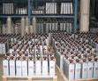
Complete condensing units for general industrial design
In the implementation of power supply systems of industrial enterprises, an increasingly wide application is found with complete, fully manufactured elements in factories. This also applies to transformer substations in stores, distribution cabinets and other elements of power systems, including capacitor banks.The use of complete devices significantly reduces the volume of construction and electrical installation work, improves their quality, reduces commissioning time, increases work reliability and safety during work.
Complete capacitor banks for voltage 380 V are produced for indoor installation, and for voltage 6-10 kV — for both indoor and outdoor use. The capacity range of these units is quite wide, and most types of modern complete capacitor units are equipped with devices for single- or multi-level automatic control of their power.
Complete capacitor units for voltage 380 V are made of three-phase capacitors, and for voltage 6-10 kV - of single-phase capacitors with a capacity of 25-75 kvar, connected in a triangle.
The complete condensing unit consists of an inlet cabinet and condenser cabinets. In 380 V installations, an automatic control device, current transformers, disconnectors, measuring devices (three ammeters and a voltmeter), control and signaling equipment and busbars are installed in the incoming cabinet.
In the case of using capacitors with built-in discharge resistors, voltage transformers are not installed. The input cubicle is fed by a cable from the 6-10 kV distribution cubicle (RU), in which the control, measurement and protection equipment is installed.