Contactless motion switches
Non-contact travel switches (rail transducers operating without mechanical action from the moving limiter) are used in control circuits for electric drives of machines, mechanisms and machines. Sensor switches are designed to switch control circuits through electromagnetic relays or contactless logic elements, which is carried out under the influence of the control element.
Classification of proximity switches
Non-contact travel switches can be classified according to: method of action on the sensitive element, physical principle of operation of the converter, design, accuracy class, degree of protection.
According to the method of influencing the sensitive element, contactless travel switches can be divided into mechanical and parametric switches.
In switches of the first type, the control element directly mechanically acts on the primary drive of the contactless limit switch, which interacts contactlessly with the sensing element.In switches of the second type, depending on the position of the control element, which is not mechanically connected to the proximity switch, a physical parameter of the transducer is changed. A certain value of this parameter changes the state of the relay element.
 The classification of non-contact travel switches according to the physical principle of operation of the converter includes the following types:
Inductive switches built on change inductance, mutual inductance as well as inductive switches.
Currently, most of the contactless travel switches on the market are inductive apparatus.
In turn, inductive proximity switch converters can be built according to the following schemes: resonant, autogenerator, differential, bridge, direct conversion.
Magnetic inductive switches that are based on the following principles: Hall effect, magnetoresistor, magnetodiode, magnetothyristor, reed switch.
Capacitive switches: with varying plate area, with varying plate gap, with varying dielectric constant of the plate gap.
Photoelectric switches with elements: photodiode, phototransistor, photoresistor, photothyristor.
Photovoltaic switches and adjacent beam switches, in which rays of a different physical nature, for example radioactive radiation, can be used together with visible light rays.
By design, contactless limit switches are divided into: slot, ring (half ring), plane, end, switches with a mechanical drive, multi-element switches.
The division of non-contact limit switches into end and planar versions is somewhat conditional, since the movement of the control element relative to the sensitive surface can, for some types of non-contact limit switches, take place both in parallel and perpendicular planes. In this case, its preferential use can be taken as a basis.
Accuracy class (the value of the basic error) contactless motion switches are divided into low (approximately ± 0.5 mm or more), medium [approximately ± (0.05-0.5) mm], increased [approximately ± (0.005-0.05) mm ] and high (approximately ± 0.005 mm or less) accuracy.
Non-contact limit switches can have different degrees of protection against ingress of foreign bodies and ingress of water into the device. The characteristics of the degree of protection of proximity sensors and the classification related to the degree of protection correspond to the characteristics and classification accepted at home and abroad for electrical equipment and electrical devices with a voltage of up to 1000 V.
Technical characteristics of proximity switches
 The technical characteristics of non-contact travel switches include precise (metrological) characteristics, speed, electrical characteristics, overall and installation dimensions and weight, nominal and permissible operating conditions, reliability indicators, price, etc.
One of the main characteristics of non-contact travel switches, which directly affects its construction and a number of other technical characteristics, is determined by the geometric arrangement of the control element relative to the sensitive surface during operation... For proximity switches in a plane, the main characteristic is taken as the working clearance — the distance between the sensitive surface of the switch and the control element on which the switch operates. The main characteristic of the limit switch is the maximum distance of influence, i.e. the maximum distance between the sensitive surface of the switch and the control element at which a change in its switching state is possible. The main characteristic of slot and ring switches is the width of the slot and the inner diameter of the ring respectively these switches.
The accuracy characteristics of contactless travel switches include the basic error, additional errors from changes in ambient temperature and changes in supply voltage, and the maximum total error. The accuracy characteristics of non-contact travel switches also include travel differential, i.e. the difference between the coordinate of the actuation point of the contactless stroke of the switch and the coordinate of the point of its disconnection when the control element is moved in the opposite direction.
Speed (response time) of the proximity switch — this is the time between the moment of establishment of the working coordinate and the moment of reaching the stationary voltage value at the output of the non-contact limit switch.Knowing the magnitude of the speed of the non-contact travel switch, it is possible to determine the dynamic errors in the operation of the non-contact travel switches when the speed of movement of the control element changes.
Electrical characteristics of proximity switches include the required parameters of the power supply (power supply) and load characteristics. The parameters of the supply network include: type of current (direct, alternating), supply voltage and its permissible deviations, level of ripples, power consumed by a proximity switch or current consumption, frequency of the network (for alternating current). The load characteristics of non-contact travel switches are the type of load (relay, chip, etc.). the output voltage, power or current drawn from the load.
Indicators of reliability and durability of non-contact limit switches include, first of all: the probability of trouble-free operation for a certain period of operation or for a certain number of operations and the service life of a non-contact limit switch.
The most important parameters should also include the overall and mounting dimensions of contactless motion switches.
Requirements for proximity switches
 One of the most important requirements for limit switches is the requirement for high reliability of their operation. Compared to other electrical equipment, including electronic, limit switches work in the most difficult conditions, because they are located directly in the working areas of process machines, where there is a wide range of temperatures, vibrations and shocks, strong electromagnetic fields, contamination from chips and different liquids are possible.
Limit switches may be required to operate at high operating frequencies at high speeds of movement of the controls.
The technical data of the contact limit switches do not always allow to meet the requirements. This is especially characteristic of automated process equipment with complex electrical equipment containing a large number contact limit switchessuch as automatic machine lines, top push conveyors and other branched conveying systems, foundry and metallurgical equipment, etc. This also applies to heavy-duty equipment with a large number of operations per unit time, such as forging and press equipment.
In many of the above cases, when contact limit switches are used, it is impossible to ensure acceptable reliability of the operation of automated technological equipment, and in addition, these switches must be periodically replaced on the working equipment due to their short service life in relation to the total number operations.
As a rule, proximity switches are highly reliable, capable of operating at a high frequency of operations, and have a long service life in terms of the total number of operations. An important advantage of contactless motion switches is that their reliability (the probability of trouble-free operation for a certain period) is practically independent of the frequency of operations.
Increasing equipment reliability when using contactless travel switches is also facilitated by the fact that contactless travel switches can only be turned on when needed.In the case of using limit switches of the contacts, the switching of the contacts takes place with each push of the cam, regardless of whether these contacts are connected to the electrical circuit or not.
Some requirements for proximity switches are also due to operating conditions.
 The main environmental conditions to consider are usually AC supply voltage and ambient temperature. Within the specified limits of changes in external conditions, non-contact limit switches must maintain operability and the required accuracy. The operation of the switches should not be significantly affected by the humidity of the surrounding air, as well as by the altitude above sea level within the limits accepted for the limit switches.
The requirements that are usually imposed on non-contact travel switches are the ability to occupy any working position in space and the absence of influence of the base material on which they are installed and the metal bodies in contact with the body of the non-contact travel. The operation of the proximity sensors must not be affected by vibrations and shocks, as well as by the penetration of oil, emulsion, water, dust.
The highest actuation frequency of non-contact travel switches when used as a load electromagnetic relay can practically reach 120 operations per minute. If electronic devices are used as the load of proximity switches, then the operating frequency of the system can be significantly higher.
Generator proximity switches
The principle of operation of contactless generator travel switches is based on changes in the parameters of the oscillating circuit of the generator under external influence. Such a changing parameter that converts the movement of the control element into a changing electrical signal is usually the inductance or capacitance of the oscillating circuit or the mutual inductance between the coils of the circuit. In contactless limit switches with an inductive generator of the end type, the control element, which is a conductive plate, introduces, when approached, a disturbance in the high-frequency electromagnetic field created by the inductive coil of the oscillator circuit.
At the same time in the control element, eddy currentscreating its own electromagnetic field. Electromagnetic field eddy currents have the opposite effect on the coil of the converter, causing changes in the active and reactive resistance in it and, therefore, a change in the oscillator output signal in frequency and amplitude from the initial values corresponding to a significant distance of the control element to the values \u200b\u200bof these parameters corresponding at that position of the control element at which there is an abrupt change in state, the threshold device. This change in the oscillator output signal is ultimately sensed by the drive.
The output signal of the oscillator is a voltage fluctuation with a frequency of several hundred kilohertz. At the output of the threshold device, this signal must arrive unipolar. Therefore, a rectifier is connected between the generator and the threshold device.
BVK-24 proximity switches
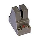 Widespread slot-type proximity switches with transistor amplifiers operating in generator mode. In fig. 1, and shows a general view of the switch type BVK-24. Its magnetic circuit, located in the box 4, consists of two ferrite cores 1 and 2 with an air gap 5-6 mm wide between them. In core 1 there is a primary winding wk and a positive feedback winding wp.c, in core 2 there is a negative feedback winding wо.s. Such a magnetic circuit eliminates the influence of external magnetic fields. The feedback coils are connected in series—opposite. As a switching element, an aluminum petal (plate) 3 with a thickness of up to 3 mm is used, which can be moved into the slot (in the air gap) of the magnetic system of the sensor.
Contactless motion switch BVK -24: a — general view; b — electrical schematic diagram
If the petal is outside the core, then the difference between the voltages induced in the windings wpc and wo.c will be positive, the transistor VT1 is closed and the generation of constant oscillations in the circuit wc — C3 (Fig. 1, b ) does not occur. When a petal is introduced into the sensor slot, the connection between the coils wk and wо.c is weakened (therefore the petal is also called a screen), a negative voltage is applied to the base of the transistor VT1 and it opens. In the circuit wk — C3 is generated and alternating current, which induces an EMF in the coil wp.c in the main circuit of the transistor. In the base circuit of the transistor VT1, the variable component of the base current is detected. The transistor opens, causing relay K to
To stabilize the operation of the transistor with fluctuations in temperature and voltage, a nonlinear voltage divider is used, consisting of a linear element — R1, a semiconductor thermistor R2 and a diode VD2.
The response error is 1-1.3mm. The supply voltage of the BVK-24 switch is 24 V.
Circuit diagram of the contactless switch BVK
Scheme of sequential switching of two contactless switches BVK
Scheme of parallel connection of two contactless switches BVK
KVD contactless switches
Non-contact limit switches of the KVD type are designed for switching electrical control and signaling circuits during automation of various systems. The circuit includes an oscillator and a transistor trigger. When a metal plate is introduced into the operating gap, a decrease in the feedback coefficient occurs, causing a breakdown in the generation, the trigger flips and a normally closed output transistor opens, which activates a relay or logic element. Supply voltage — 12 or 24 V
Non-contact limit switches BTB
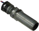 BTB switches are designed for switching control circuits by means of relays or by matching elements of non-contact logic elements. The switches change the switching state (action) when approaching the sensitive element of the structural steel control element. The switches work on the principle of a controlled generator, switching occurs when approaching the sensitive element of the controlled part or control element made of structural steel.
All switches are equipped with protection circuits against reverse polarity of the supply voltage and overvoltage when switching off inductive loads. Switches BTP 103-24, BTP 211-24-01 and BTP 301-24, in addition to the above protection schemes, are equipped with a protection circuit against overload and short circuit in the freight chain. Supply voltage of BTB switches — 24 V.